

Centrifuge
A centrifuge and guide rod technology, applied in the field of centrifuges, can solve the problems of high price and cost, and achieve the effects of low production cost, simple principle and structure, and stable equipment
- Summary
- Abstract
- Description
- Claims
- Application Information
AI Technical Summary
Problems solved by technology
Method used
Image

Examples
Embodiment Construction
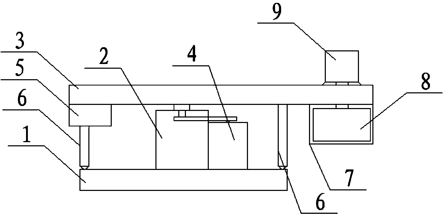
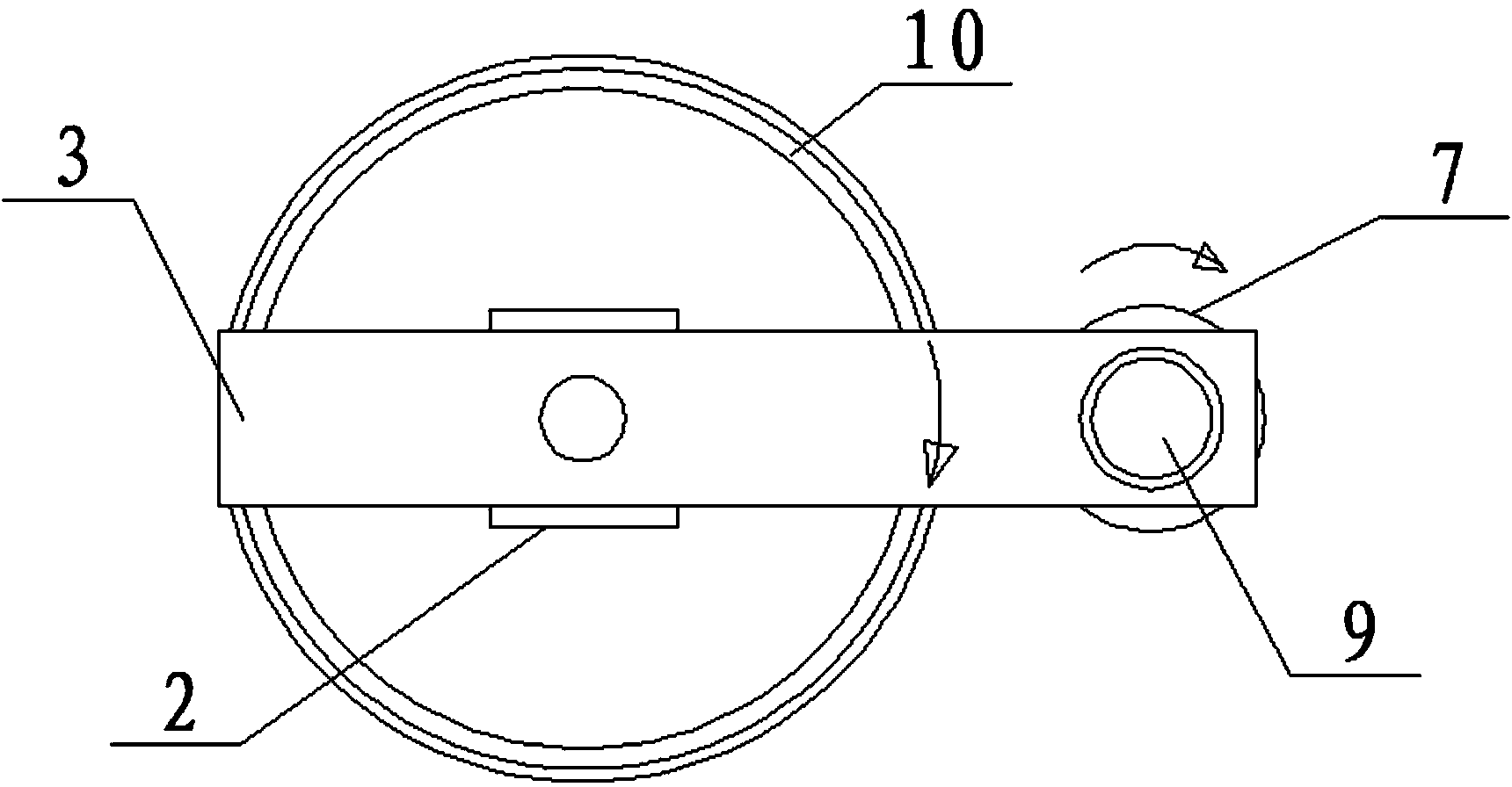
[0013] Referring to the accompanying drawings, a centrifuge includes a bottom plate 1 and a rotating base 2. It is characterized in that: the rotating base 2 is provided with a rotating guide rod 3, and the rotating guide rod 3 is connected to the motor located on the side of the rotating base 2 through a belt. one 4
[0014] Above, the end of one side of the rotating guide rod 3 is provided with a counterweight 5, the bottom of the counterweight 5 is provided with a supporting structure 6, the other end of the rotating guide rod 3 is provided with a drum 8, and the rotating The drum 8 is connected to the motor 2 9 positioned above the rotating guide rod, and the other side of the rotating guide rod 3 is provided with a supporting structure 6; the described base plate 1 is a circular structure, and the described base plate 1 is provided with a The structure 6 slides the annular track 10;: the support structure 6 is a support rod, and the bottom of the support rod is provided w...
PUM
 Abstract
Description
Claims
Application Information