Sliding Precast Forming Machine

A technology of prefabricated components and forming machines, which is applied in the direction of ceramic forming machines and manufacturing tools, which can solve the problems of low production efficiency, occupying the molding cavity of equipment, and inability to produce concrete prefabricated components.

Active Publication Date: 2016-03-23
DEZHOU HAITIAN ELECTROMECHANICAL TECH
View PDF4 Cites 0 Cited by
  • Summary
  • Abstract
  • Description
  • Claims
  • Application Information

AI Technical Summary

Problems solved by technology

[0002] The existing mobile equipment concrete forming technology is to drop concrete into the equipment forming cavity through the equipment hopper, push the concrete with the pushing device in the equipment, and push and vibrate the concrete to vibrate and form the concrete, and the formed concrete is attached to the site , continuous pushing and vibrating action, the formed concrete does not move, and the equipment is pushed forward by the reaction force to realize the walking of the equipment. However, this working principle requires a pushing device to push the concrete to realize the walking of the equipment. This device occupies the equipment. For all the space in the forming cavity, if the concrete embedded parts or transverse steel bars are placed in front of the equipment in advance, the existing equipment will not work normally, which is why the existing technology cannot produce concrete prefabricated components with embedded parts and transverse steel bars shortcoming
Thus limiting the development of the two models
If it is necessary to realize the above-mentioned technologies, it can only be realized by using fixed molds, but the production efficiency of fixed molds is low and the cost is high, resulting in low demand from customers.
With the continuous development of the concrete component industry, the demand for large-span prefabricated components in the construction industry is increasing day by day. Small forming machines cannot produce super-long-span prefabricated components at all, and the prices of products produced by molds are particularly high, which limits the development of the concrete industry.

Method used


Image

  • Sliding Precast Forming Machine
  • Sliding Precast Forming Machine
  • Sliding Precast Forming Machine

Examples


Embodiment Construction

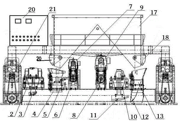
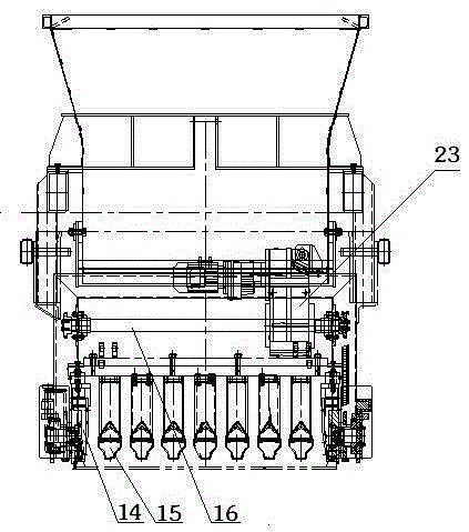
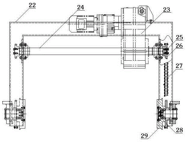
[0010] Referring to the accompanying drawings, a sliding prefabricated component forming machine includes a frame 1, a first vibrator 2, a rear vibrating plate 3, a first material limiting plate 4, a rear distribution box 5, a material box drive shaft 6, a material Box drive shaft motor 7, mold drive shaft 8, mold drive shaft motor 9, second vibrator 10, front vibrating plate 11, second material limiting plate 12, front distribution box 13, side template 14, mandrel 15, mold The connection beam 16, the main material box 17, the front material door 18 of the main material box, the rear material door 19 of the main material box and the power distribution cabinet 20 are characterized in that: the front and rear sides of the frame 1 are respectively provided with a walking device 21, Described walking device 21 is provided with walking frame 22, and walking frame 22 is provided with variable frequency deceleration motor 23, and on the variable frequency deceleration motor 23, wears...


PUM


Abstract

The invention relates to a sliding-type prefabricated-member forming machine. The sliding-type prefabricated-member forming machine is characterized in that traveling devices (21) are arranged on the front side and the rear side of a machine frame (1) respectively, each traveling device (21) is provided with a traveling frame (22) which is provided with a variable frequency speed-reduction motor (23), a traveling transmission shaft (24) penetrates through each variable frequency speed-reduction motor (23), the two ends of each traveling transmission shaft (24) are fixed to the corresponding traveling frame (22) through bearings (25) respectively, the two ends of each traveling transmission shaft (24) are respectively provided with a chain wheel (26), each chain wheel (26) is connected with a driven chain wheel (28) through a chain (27), a traveling wheel (29) is arranged on each driven chain wheel (28), and the traveling wheels (29) travel on rails (30). A pre-embedded part and a steel wire mesh are fixed in a forming-machine traveling path in advance, the sliding-type prefabricated-member forming machine can work normally, concrete is combined with the pre-embedded part and the steel wire mesh which are prefabricated, and a product needed by the market is obtained.

Description

technical field [0001] The invention belongs to the technical field of manufacturing cement product forming equipment, and in particular relates to a sliding type prefabricated component forming machine. Background technique [0002] The existing mobile equipment concrete forming technology is to drop concrete into the equipment forming cavity through the equipment hopper, push the concrete with the pushing device in the equipment, and push and vibrate the concrete to vibrate and form the concrete, and the formed concrete is attached to the site , continuous pushing and vibrating action, the formed concrete does not move, and the equipment is pushed forward by the reaction force to realize the walking of the equipment. However, this working principle requires a pushing device to push the concrete to realize the walking of the equipment. This device occupies the equipment. For all the space in the forming cavity, if the concrete embedded parts or transverse steel bars are pla...

Claims


Application Information

Patent Timeline
Patent Type & Authority Patents(China)
IPC IPC(8): B28B1/087
CPCB28B1/087B28B1/084
Inventor 于海滨蔡海宁
Owner DEZHOU HAITIAN ELECTROMECHANICAL TECH
Why Eureka
Try Eureka