A new type of sucker

A suction cup, a new type of technology, applied in the direction of suction cups, connecting components, mechanical equipment, etc., can solve the problems of poor adsorption, damage, hand injury, etc., and achieve the effect of overcoming weak adsorption, strong adsorption capacity, and exquisite structure

Active Publication Date: 2016-08-24
SHANGHAI HUAN HSIN ELECTRONICS
View PDF5 Cites 0 Cited by
  • Summary
  • Abstract
  • Description
  • Claims
  • Application Information

AI Technical Summary

Problems solved by technology

One is: it is composed of a rubber disc, a screw, a cover and a rotating disc with nuts / threads. By connecting a threaded rod on the back of the rubber disc, the screw passes through the cover, and then connects with the screw, and passes through the rotation of the rotating disc. The rotation creates a vacuum between the rubber disc body and the wall, resulting in adsorption; the installation efficiency of the suction cup with this structure is low, and it is easy to leak gas between the rubber disc body and the wall during the installation process, resulting in weak adsorption; the other is: It is composed of a rubber disc body, a pull rod, a spring and a breaker. Through the principle of leverage, the breaker is forced to move the breaker to realize the tension and relaxation of the pull rod, and then realize the deformation and restoration of the rubber disc body; this structure is more laborious. , and the breaking piece is easy to be broken due to excessive force, causing damage. At the same time, it is easy to cause damage to the user's hand

Method used


Image

  • A new type of sucker
  • A new type of sucker
  • A new type of sucker

Examples


Embodiment Construction

[0023] The present invention is described in further detail below in conjunction with accompanying drawing:

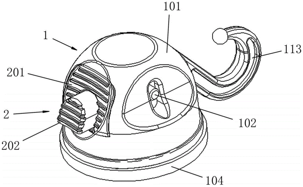
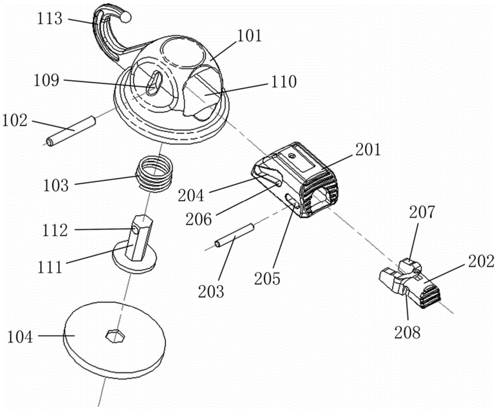
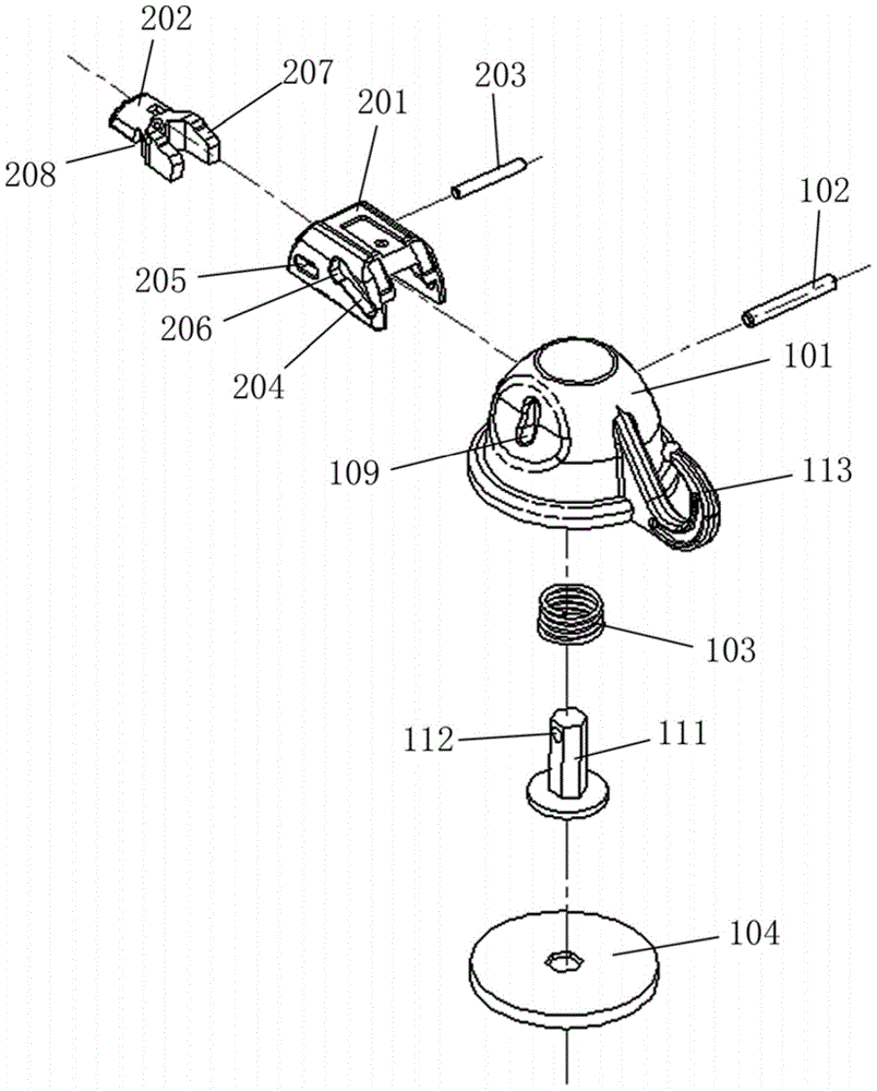
[0024] like Figure 1-Figure 7 As shown, a new suction cup includes a body 1 and a control mechanism 2; the control mechanism 2 includes a push block 201, a return switch 202 and a fixed pin 203, and the push block 201 is provided with an inclined chute 204 and a fixed hole 205, the upper end of the chute 204 is provided with a card position 206, and the return switch 202 is provided with an inclined-plane push portion 207 and a small waist-shaped hole 208, and the fixed pin 203 passes through the fixed hole 205, the small waist-shaped hole 208 to The return switch 202 is fixed on the push block 201; the body 1 includes a cover 101, a bayonet pin 102, a spring 103 and a disc body 104, the inner cavity of the cover 101 is provided with a partition 105, and the center of the partition 105 is provided with a through hole 106, forming a connected control mechanism cavity ...


PUM


Abstract

The invention discloses a novel sucker, which includes a body and a control mechanism, the control mechanism includes a push block, a return switch and a fixing pin, the push block is provided with an inclined chute and a fixing hole, and the upper end of the chute is provided with a locking position , the return switch is provided with a sloped push part and a small waist-shaped hole, and the return switch is fixed on the push block; the body includes a cover, a bayonet, a spring and a disc body; a connected control mechanism cavity and a spring telescopic are formed in the cover. There are waist-shaped holes on the two side walls of the control mechanism cavity, and a control mechanism installation hole on the other side wall. There is a pull rod on the back of the disc body, and a bayonet hole is set on the upper part of the pull rod. Enter the cavity of the control mechanism through the through hole of the partition plate, and fix the disk body through the bayonet hole, the bayonet hole and the chute through the bayonet pin. Compared with the prior art, the present invention has the advantages of overcoming the disadvantages of poor adsorption of traditional rotary suction cups and easy damage of flip-type suction cups, compact structure, convenient use, strong adsorption capacity, and not easy to damage.

Description

technical field [0001] The invention relates to daily necessities, in particular to a novel sucker. Background technique [0002] There are generally two types of traditional suction cups. One is: it is composed of a rubber disc, a screw, a cover and a rotating disc with nuts / threads. By connecting a threaded rod on the back of the rubber disc, the screw passes through the cover, and then connects with the screw, and passes through the rotation of the rotating disc. The rotation creates a vacuum between the rubber disc body and the wall, resulting in adsorption; the installation efficiency of the suction cup with this structure is low, and it is easy to leak gas between the rubber disc body and the wall during the installation process, resulting in weak adsorption; the other is: It is composed of a rubber disc body, a pull rod, a spring and a breaker. Through the principle of leverage, the breaker is forced to move the breaker to realize the tension and relaxation of the pu...

Claims


Application Information

Patent Timeline
Patent Type & Authority Patents(China)
IPC IPC(8): F16B47/00
Inventor 徐钲鑑
Owner SHANGHAI HUAN HSIN ELECTRONICS
Why Eureka
Try Eureka