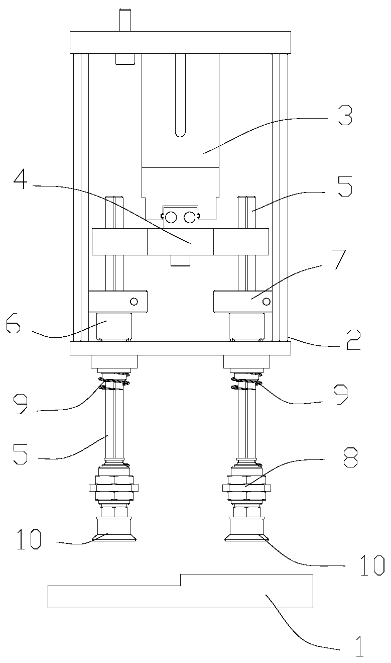
Automatic carrying device for spring cover machining

A technology of handling device and spring cover, which is applied in the field of mechanical processing, can solve the problems of height difference between the end faces of the spring cover, high manufacturing cost, troublesome operation, etc., and achieve the effect of avoiding unreliability

Inactive Publication Date: 2020-07-17
南通瑞斯电子有限公司
View PDF7 Cites 0 Cited by
  • Summary
  • Abstract
  • Description
  • Claims
  • Application Information

AI Technical Summary

Problems solved by technology

[0003] The technical problem to be solved by the present invention is that after the spring cover is processed, there will be a difference in height on the end surface of the spring cover, which brings troubles to the automatic conveying device. The automatic conveying device in the prior art is either complicated in structure and high in manufacturing cost, or It is necessary to change the type of suction cup to make up for the height difference of the product, and the operation is troublesome. The invention provides an automatic handling device for spring cover processing to solve the above problems

Method used


Image

  • Automatic carrying device for spring cover machining

Examples


Embodiment Construction

[0011] Embodiments of the present invention are described in detail below, examples of which are shown in the drawings, wherein the same or similar reference numerals designate the same or similar elements or elements having the same or similar functions throughout. The embodiments described below by referring to the figures are exemplary only for explaining the present invention and should not be construed as limiting the present invention. On the contrary, the embodiments of the present invention include all changes, modifications and equivalents coming within the spirit and scope of the appended claims.

[0012] In describing the present invention, it should be understood that the terms "center", "longitudinal", "transverse", "length", "width", "thickness", "upper", "lower", "front", " Back", "Left", "Right", "Vertical", "Horizontal", "Top", "Bottom", "Inner", "Outer", "Axial", "Radial", "Circumferential", etc. The indicated orientation or positional relationship is based ...


PUM


Abstract

The invention provides an automatic carrying device for spring cover machining. The automatic carrying device is used for carrying a spring cover with the surface being provided with high-low difference faces. The automatic carrying device comprises a rack and a driving air cylinder which is fixedly arranged on the rack. The automatic carrying device further comprises clamping mechanisms. The number of the clamping mechanisms is two, and the two clamping mechanisms are both arranged on a piston rod of the driving air cylinder. The piston rod of the driving air cylinder operates to be able to drive the clamping mechanisms to move up and down, a pressing block can be driven by the driving air cylinder to push clamping sleeves to move downwards, and meanwhile connecting plates can be ejectedto move downwards under the effect of springs, so that suction nozzles on the connecting plates are driven to adsorb the spring cover. When the height of the upper end face of the left portion of thespring cover is different from that of the upper end face of the right portion of the spring cover, the effect that the left suction nozzle and the right suction nozzle can adsorb the spring cover canbe guaranteed under the action of the springs, and single-side adsorption unreliability is avoided.

Description

technical field [0001] The invention relates to the field of mechanical processing, in particular to an automatic conveying device for spring cover processing. Background technique [0002] After the spring cover is processed, there will be a difference in height on the end surface of part of the spring cover, which brings trouble to the automatic handling device. The automatic handling device in the prior art is either complex in structure and high in manufacturing cost, or needs to replace the type of suction cup to make up for the product. The height difference makes the operation troublesome. Contents of the invention [0003] The technical problem to be solved by the present invention is that after the spring cover is processed, there will be a difference in height on the end surface of the spring cover, which brings troubles to the automatic conveying device. The automatic conveying device in the prior art is either complicated in structure and high in manufacturing ...

Claims


Application Information

Patent Timeline
Patent Type & Authority Applications(China)
IPC IPC(8): B23Q7/04B25J15/06B65G47/91
CPCB23Q7/043B25J15/0616B65G47/918
Inventor 曹维富陈荣
Owner 南通瑞斯电子有限公司
Why Eureka
Try Eureka