Method of Measuring Bohr Resonance Phase Difference Using Photogate

A technology of Bohr resonance and Bohr resonance instrument is applied in the field of physical experimental parameter measurement, which can solve the problems of reduced flash, insufficient partial pressure of experimental instruments, abnormal working state of electronic circuits of measuring instruments, etc., so as to expand thinking ability and avoid influence. Effect

Inactive Publication Date: 2016-03-09
SICHUAN UNIV
View PDF3 Cites 0 Cited by
  • Summary
  • Abstract
  • Description
  • Claims
  • Application Information

AI Technical Summary

Problems solved by technology

[0007] Due to the high current of the flash lamp, the internal partial voltage of the experimental instrument is insufficient when the flash lamp is used, which may cause abnormal working status of the electronic circuit of the measuring instrument. It has been found in the experiment that the displayed cycle data has abnormal changes, usually when the flash occurs. The significant reduction has caused many students to question: Is the phase difference data accurate?

Method used


Image

  • Method of Measuring Bohr Resonance Phase Difference Using Photogate
  • Method of Measuring Bohr Resonance Phase Difference Using Photogate

Examples


Embodiment Construction

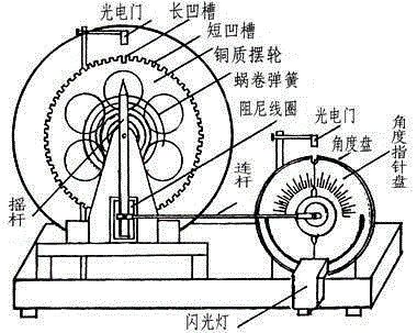
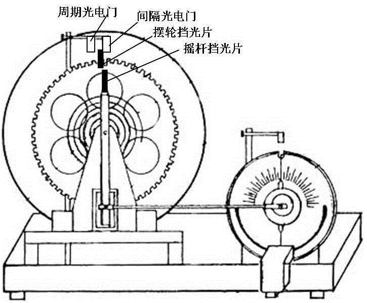
[0012] The method for measuring the phase difference of Bohr resonance by using a photogate, the steps are:

[0013] The first step is to fix a rocker light shield on the top of the rocker of the Bohr resonance instrument, fix a balance wheel light shield on the upper end of the balance wheel of the Bohr resonance instrument, the rocker light shield and the balance wheel light shield The widths are equal and the tops are equal (the tops are flush), so that there is a kind of equality when blocking the light of the photoelectric gate; the balance wheel light blocking plate is made of iron material, and a magnet block and the balance wheel light blocking plate are respectively located on the balance wheel. The two sides of the wheel are fixed by mutual attraction of iron material and magnet blocks, which is convenient for moving the position of the balance wheel light barrier.

[0014] Step 2: Fix an interval photogate for measuring the time interval on a bracket, adjust the pos...


PUM


Abstract

The invention provides a method for measuring a Pohl resonance phase difference by using photogates and relates to the field of physical experiment parameter measurement. The method replaces a stroboscopic method for measuring the Pohl resonance phase difference. According to the technical scheme, a rocker light blocking piece is fixed to the top of a rocker of a Pohl resonance instrument, a swing wheel light blocking piece is fixed to the upper end of a swing wheel, the swing wheel light blocking piece and the rocker light blocking piece can both pass through the interval photogate in the swing process, and the interval photogate is made to start timing or stop timing. The swing wheel light blocking piece or the rocker light blocking piece passes through the cyclic photogate in the swing process. After forced vibration is stabilized, the time difference delta T of the swing wheel light blocking piece and the rocker light blocking piece arriving at the same position is measured through the interval photogate, the swing cycle T is measured through the cyclic photogate, and the phase difference is 360-degree*delta T / T. The method for measuring the Pohl resonance phase difference by using the photogates has the advantages that a flash lamp is not used, and thus the influences of large currents on the working state of an electronic circuit are avoided; the method for replacing the stroboscopic method for measuring the phase difference is proposed, and the prior art is enriched.

Description

technical field [0001] The invention relates to the field of physical experiment parameter measurement, in particular to the measurement of the phase difference between an external force and a balance wheel when a Bohr resonance instrument is forced to vibrate. Background technique [0002] In the university physics laboratory, the Bohr resonance instrument generally uses the stroboscopic method to measure the phase difference between the external force and the balance wheel. The experimental device is as follows: figure 1 . [0003] Device structure: the angle disc is fixed on the outside of the motor. The angle disc is not connected with the motor shaft and is in a static state, that is, it does not rotate with the motor shaft. The angle disc and the motor shaft have a common center of circle. The upper semicircle of the angle disc has a scale. The minimum scale is 1 degree; the outside of the angle disc is the angle pointer disc, which is a plastic disc, and the angle po...

Claims


Application Information

Patent Timeline
Patent Type & Authority Patents(China)
IPC IPC(8): G09B23/18
Inventor 胡再国雍志华张俊峰梁雅庭邹旭敏穆万军朱俊饶大庆罗明蓉李娟程艳王维果刘石丹李伟于白茹梁小冲李紫源
Owner SICHUAN UNIV
Why Eureka
Try Eureka