
A non-slip pressure roller

A pressing roller and roller technology, applied in the field of crushing equipment, can solve the problems of looseness, axial movement and high production cost, and achieve the effects of convenient maintenance, avoiding axial movement and avoiding slippage

Active Publication Date: 2016-08-17
湖南宇晖重工机械有限公司
View PDF7 Cites 0 Cited by
  • Summary
  • Abstract
  • Description
  • Claims
  • Application Information

AI Technical Summary

Problems solved by technology

The pressure roller of the former form, when the roller is worn out, is scrapped together with the hub, resulting in high production cost
Although the latter type of pressure roller can be replaced to reduce production costs, but because it is only driven by the conical surfaces at both ends, it will loosen after a period of use, and there will be axial movement or slippage. (i.e.: the hub is idling), or even cut off the connecting bolts, resulting in the failure of the roller sand making machine to work normally.

Method used


Image

  • A non-slip pressure roller
  • A non-slip pressure roller

Examples


Embodiment Construction

[0010] The present invention will be further described below in conjunction with the accompanying drawings and embodiments. The following description is by way of example, but the protection scope of the present invention should not be limited thereto.

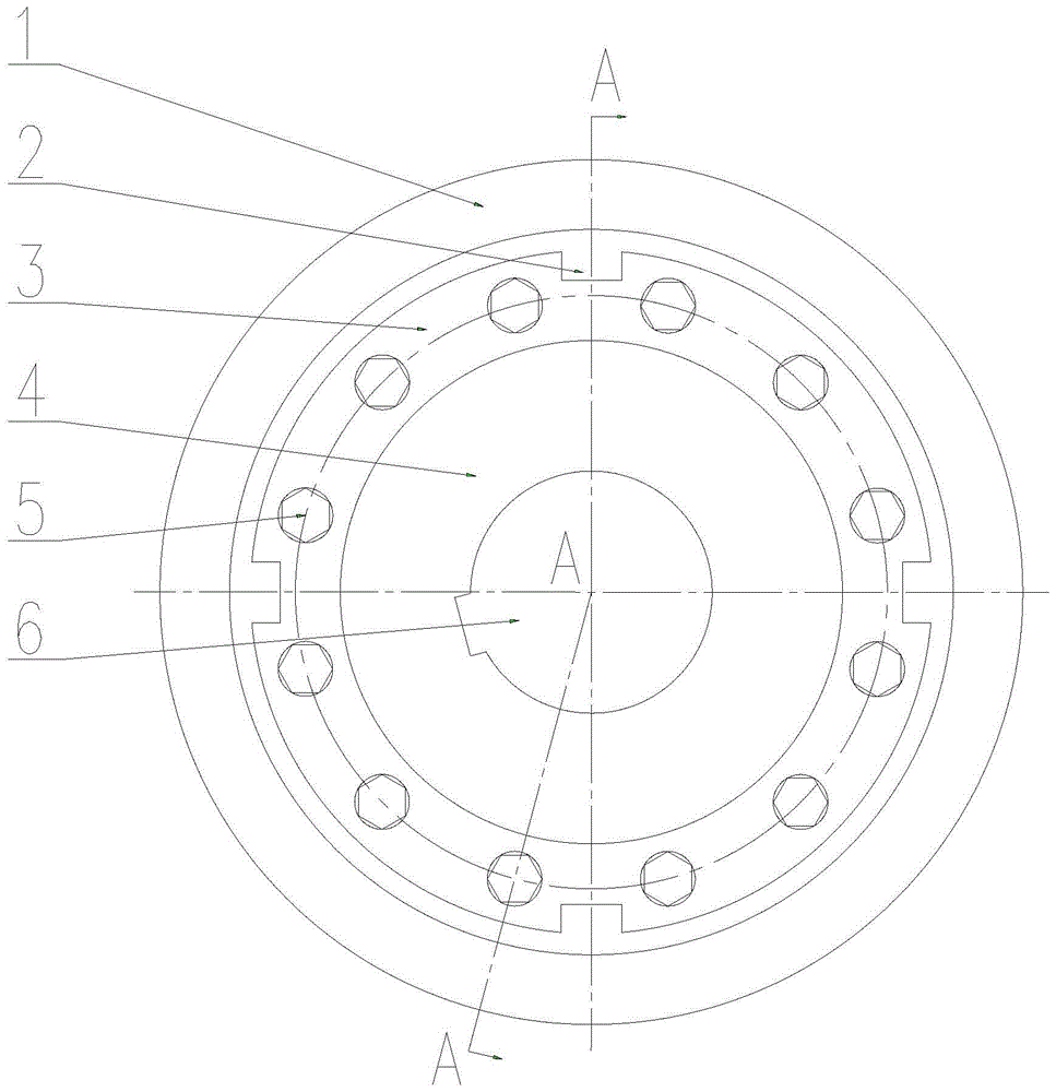
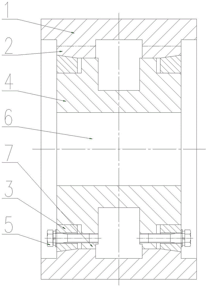
[0011] The present embodiment is made up of roller 1, wheel hub 4 and conical pressure ring 3.

[0012] Roller 1 is a cylinder made of high wear-resistant material, and four (or two or three or more) axial convex strips 2 (the cross-section of the axial convex strips are usually Rectangular shape, also can be other shapes); At the two ends of the inner hole of the roller 1, respectively form a slope-like inner cone with a large outside diameter and a small inside diameter.

[0013] The conical pressure ring 3 is a circular ring whose outer cylindrical surface is a conical surface and the inner wall is a cylindrical surface. 2 notches).

[0014] In the middle of the hub 4, there is a hub shaft hole 6 for wearing the hub shaf...


PUM


Abstract

The invention discloses a non-slip pressure roller, which relates to the technical field of crushing equipment, and includes a roller 1 and a hub 4, and the roller 1 is set on the hub 4; on the inner wall of the roller 1, there are more than one axial The convex line 2; a groove matching the axial convex line 2 is provided on the outer cylindrical surface of the hub 4; it has the characteristics of convenient maintenance and no slipping phenomenon, and is used in conjunction with the double-roller sand making machine. It can be used to prepare sand for construction using sandstone, pebbles and other materials, and can also be used for pre-grinding in the grinding system; it can be widely used in construction, building materials, mining and other fields.

Description

technical field [0001] The invention relates to the technical field of crushing equipment, in particular to an anti-slip pressure roller. Background technique [0002] In the prior art, there are mainly two types of pressure rollers used in the double-roller sand making machine. One is the integral casting type, that is, the roller and the hub are cast as one; the other is the roller and the wheel. The hub is manufactured separately, and then the roller is set on the hub, and the roller and the hub are fixed as a whole by the compression ring at both ends. The pressure roller of the former form is scrapped together with the hub after the roller wears out, resulting in excessively high production costs. Although the latter type of pressure roller can be replaced to reduce production costs, but because it is only driven by the conical surfaces at both ends, it will loosen after a period of use, and there will be axial movement or slippage. (i.e.: the hub idling), or even cut...

Claims


Application Information

Patent Timeline
Patent Type & Authority Patents(China)
IPC IPC(8): B02C4/30
Inventor 谢宇
Owner 湖南宇晖重工机械有限公司
Learn More