Multipoint positioning auxiliary device

An auxiliary device, multi-point positioning technology, applied in manufacturing tools, workshop equipment, etc., can solve the problems of inconvenient operation, difficult to carry tools, large size, etc., to improve positioning accuracy, facilitate storage and portability, and expand the scope of application. Effect

Active Publication Date: 2014-09-10
STATE GRID CORP OF CHINA +2
View PDF8 Cites 14 Cited by
  • Summary
  • Abstract
  • Description
  • Claims
  • Application Information

AI Technical Summary

Problems solved by technology

[0002] In the daily work of the power company, it is necessary to install various boxes and brackets. Usually, in the installation operation, it is necessary to mark the corresponding holes on the corresponding walls and other surfaces according to the distribution of the installation holes on the objects to be installed. The location of the installation hole can usually be determined by the following methods: 1) Manually place the object to be installed on the surface of the wall, and mark it on the surface of the wall according to the location of the installation hole, but some objects are large in size and heavy in weight , which makes the operation inconvenient. At the same time, the positions of the mounting holes on some objects are relatively hidden, and it is not easy to make comparison marks; 2) By measuring the distance between the mounting holes, use a scale to mark the surface of the wall, but this method will lead to installation problems. The operation is cumbersome, and the installation is tilted and unsightly; 3) Auxiliary devices such as punching templates are used for auxiliary installation. The existing installation hole positioning auxiliary devices are basically composed of several scales, such as the Chinese patent application CN201310646287.0 A meter box installation auxiliary tool and its use method, Chinese patent application CN201310427075.3 A meter box installation locator, etc. These auxiliary tools have the following disadvantages: they are large in size and cannot be stored, making these tools not easy to carry; It can only locate the installation holes with relatively regular position distribution, such as four-hole distribution in square or rectangular distribution; the number of positioning holes is limited, and only a small number of holes can be positioned; it cannot be positioned on non-planar wall surfaces , these auxiliary tools cannot work on relatively narrow surfaces

Method used


Image

  • Multipoint positioning auxiliary device
  • Multipoint positioning auxiliary device
  • Multipoint positioning auxiliary device

Examples


Embodiment Construction

[0031] The present invention will be described in further detail below in conjunction with the accompanying drawings.

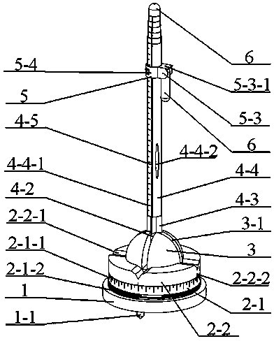
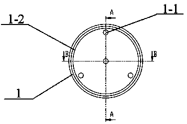
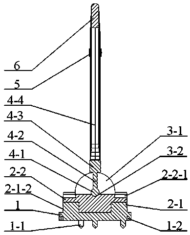
[0032] The structure diagram of the present invention is as figure 1 As shown, it includes a cylindrical base 1, a cylindrical indexing and positioning mechanism 2, a hemispherical positioning seat 3, a cylindrical scale rod 4, a positioning vernier 5, and a marking device 6.

[0033] The indexing and positioning mechanism 2 is arranged on the base 1, and the indexing and positioning mechanism 2 includes an indexing plate 2-1 and a counter-fixing plate 2-2, and the indexing plate 2-1 and the counter-fixing plate 2-2 are relatively rotatable; The circumferential scale scale 2-1-1 is set on the upper edge of the circumferential surface of the indexing plate 2-1, and the thread 2-1-2 is set on the lower edge of the circumferential surface of the indexing plate 2-1; the positioning is set on the fixed plate 2-2 The number of wing slots 2-2-1 and positioning wing...


PUM


Abstract

The invention relates to a multipoint positioning auxiliary device. The multipoint positioning auxiliary device comprises a cylindrical base and a cylindrical indexing and positioning mechanism on the base. The indexing and positioning mechanism comprises an indexing disc and an aligning disc which can rotate relatively, the aligning disc is provided with a hemispherical positioning base, the positioning base is provided with a cross positioning groove penetrating through the hemisphere, a positioning wing groove is formed in the position, corresponding to the notch of the cross positioning groove, of the aligning disc, a spherical positioning groove is formed in the centre of sphere of the positioning base, a universal ball connected with a cylindrical scale pole is embedded in the spherical positioning groove, a positioning rod and a positioning wing are arranged between the universal ball and a scale pole body in sequence, the positioning rod is matched with the cross positioning groove, the section of the positioning rod is square, the positioning wing is matched with the positioning wing groove, and a positioning vernier which can slide along the scale pole body is arranged on the scale pole. The multipoint positioning auxiliary device has the advantages of being simple in structure, accurate in positioning, convenient to operate, store and carry and the like, multipoint positioning can be achieved conveniently and rapidly, operation is simplified, and working efficiency is improved.

Description

technical field [0001] The invention relates to a tool for point positioning, in particular to an auxiliary device for multi-point positioning. Background technique [0002] In the daily work of the power company, it is necessary to install various boxes and brackets. Usually, in the installation operation, it is necessary to mark the corresponding holes on the corresponding walls and other surfaces according to the distribution of the installation holes on the objects to be installed. The location of the installation hole can usually be determined by the following methods: 1) Manually place the object to be installed on the surface of the wall, and mark it on the surface of the wall according to the location of the installation hole, but some objects are large in size and heavy in weight , which makes the operation inconvenient. At the same time, the positions of the mounting holes on some objects are relatively hidden, and it is not easy to make comparison marks; 2) By mea...

Claims


Application Information

Patent Timeline
Patent Type & Authority Applications(China)
IPC IPC(8): B25H7/00
Inventor 曹建立王学彬孙立成郑立伟李凤强魏敬珍朱向安
Owner STATE GRID CORP OF CHINA
Why Eureka
Try Eureka