
A sewing machine automatic presser foot lifting mechanism

A sewing machine and presser foot lifting technology, applied in the field of automatic presser foot lifting mechanism of sewing machines, can solve the problems of the overall structure of the presser foot lifting mechanism is not compact, the driving stroke and driving force are large, and the volume of the electromagnet is large, so as to achieve compact structure and drive Short stroke and small volume

Active Publication Date: 2015-12-02
JACK SEWING MASCH CO LTD
View PDF8 Cites 0 Cited by
  • Summary
  • Abstract
  • Description
  • Claims
  • Application Information

AI Technical Summary

Problems solved by technology

[0004] The presser foot lifting mechanism of the overlock sewing machine in the prior art includes a manual presser foot lifting mechanism and an automatic presser foot lifting mechanism. The automatic presser foot lifting mechanism of the overlock sewing machine in the prior art realizes the conversion of the driving force through two lever mechanisms. To reach the stroke of the presser foot, the direction of the driving force has to be changed by 90 degrees during the conversion process, resulting in a large amount of force loss, resulting in a large driving stroke and driving force of the electromagnet as the driving source, so the volume of the electromagnet is large. , The economic cost is high, and the overall structure of the presser foot lifting mechanism is not compact, the volume is large, and the stability is poor

Method used


Image

  • A sewing machine automatic presser foot lifting mechanism
  • A sewing machine automatic presser foot lifting mechanism
  • A sewing machine automatic presser foot lifting mechanism

Examples


Embodiment Construction

[0039] The implementation of the present invention will be illustrated by specific specific examples below, and those skilled in the art can easily understand other advantages and effects of the present invention from the contents disclosed in this specification.

[0040] see Figure 1 to Figure 3 . It should be noted that the structures, proportions, sizes, etc. shown in the drawings attached to this specification are only used to match the content disclosed in the specification, for those who are familiar with this technology to understand and read, and are not used to limit the implementation of the present invention. Limiting conditions, so there is no technical substantive meaning, any modification of structure, change of proportional relationship or adjustment of size, without affecting the effect and purpose of the present invention, should still fall within the scope of the present invention. The disclosed technical content must be within the scope covered. At the sa...


PUM


Abstract

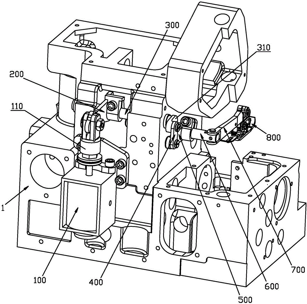
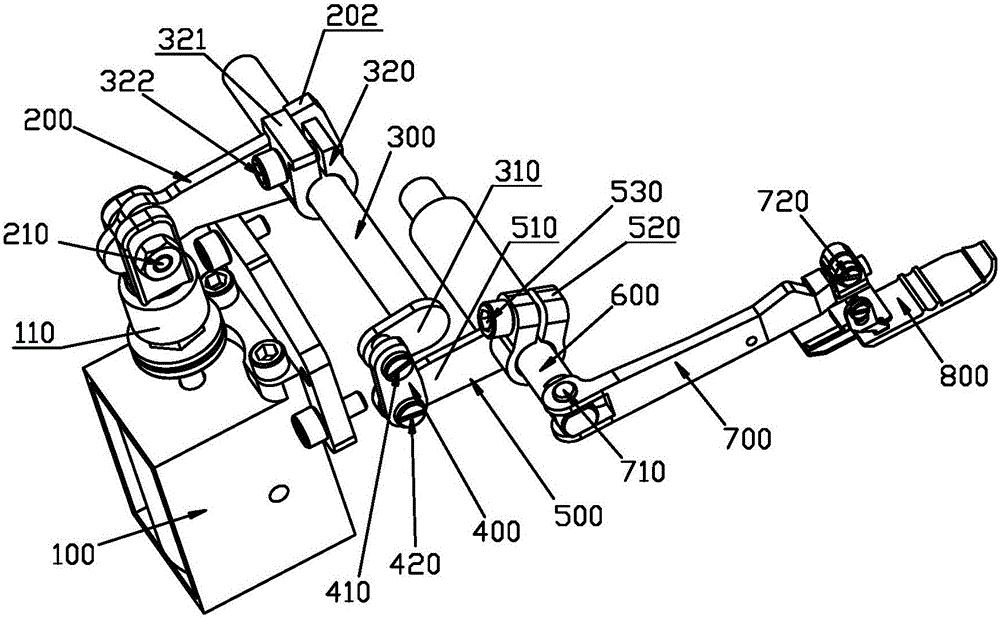
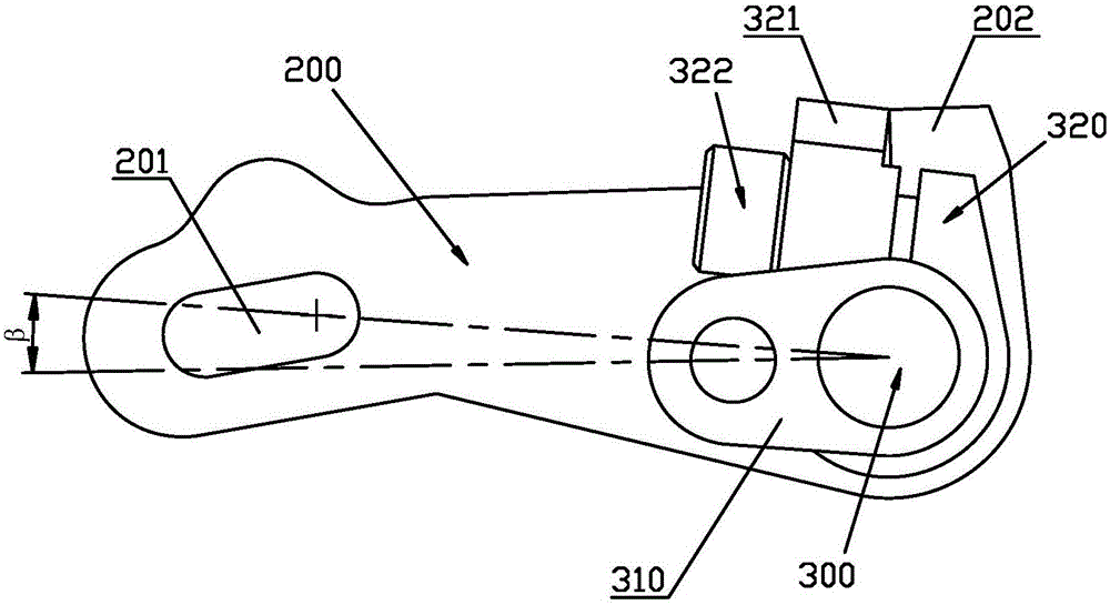
The invention provides an automatic presser foot lifting mechanism for a sewing machine. The automatic presser foot lifting mechanism comprises a drive source, a first lever, a first transmission shaft, a pull rod, a second lever, a second transmission shaft, a presser foot arm and a presser foot. The drive source comprises a telescoping shaft. One end of the first lever is vertically hinged to the first transmission shaft. A transmission boss is disposed between the first lever and the first transmission shaft. The other end of the first lever is movably connected with the upper end of the telescoping shaft. The second lever is vertically fixed with the second transmission shaft. The first transmission shaft and the second transmission shaft are horizontally disposed and parallel with each other. Two ends of the presser foot arm are respectively vertically hinged to the presser foot and the second transmission shaft. The swing direction, relative to the presser foot arm, of the presser foot is vertical to the swing direction, relative to the second transmission shaft, of the presser foot arm. The first transmission shaft is provided with a lever arm which is vertical to the axial direction of the first transmission shaft. The lever arm is connected with the second lever through the pull rod. The lever arm and the second lever are located on the same side of the pull rod. The automatic presser foot lifting mechanism has the advantages that force conversion between the first lever and the second lever is achieved on the same direction, the drive source is short in travel and compact and stable in structure, and low production cost is achieved.

Description

technical field [0001] The invention relates to the technical field of sewing equipment, in particular to an automatic presser foot lifting mechanism of a sewing machine. Background technique [0002] With the rapid development of science and technology, the degree of mechanization of clothing manufacturing is getting higher and higher. In the field of clothing manufacturing technology, there are many sewing equipment mainly based on sewing machines, such as lockstitch sewing machines, overlock sewing machines, interlock sewing machines, etc. [0003] Overlock sewing machine is also called side car and edge machine. Its main function is to prevent the seam of the garment from fluffing. The stitches of the overlock sewing machine are mesh-shaped. T-shirts, sportswear, underwear, knitting and other fabrics, widely used, is the necessary sewing equipment for large garment factories. [0004] The presser foot lifting mechanism of the overlock sewing machine in the prior art inc...

Claims


Application Information

Patent Timeline
Patent Type & Authority Patents(China)
IPC IPC(8): D05B29/02D05B29/06
Inventor 符志诚徐永明赵林蔚
Owner JACK SEWING MASCH CO LTD
Learn More