Adaptive fan-cooled LED lamp tube

An LED lamp tube and self-adaptive technology, applied in the field of non-portable indoor lighting lamps, to achieve the effects of improving heat dissipation efficiency, good air intake effect and high heat dissipation efficiency

Active Publication Date: 2014-09-10
宁波丽安电子有限公司
View PDF5 Cites 56 Cited by
  • Summary
  • Abstract
  • Description
  • Claims
  • Application Information

AI Technical Summary

Problems solved by technology

However, the LED tubes currently on the market do not have a special optimization design for the shape of the heat sink on the surface of the heat dissipation aluminum plate and how to cooperate with the heat dissipation fan, so in fact, further research and improvement can be carried out on these two aspects

Method used


Image

  • Adaptive fan-cooled LED lamp tube
  • Adaptive fan-cooled LED lamp tube
  • Adaptive fan-cooled LED lamp tube

Examples


Embodiment 1

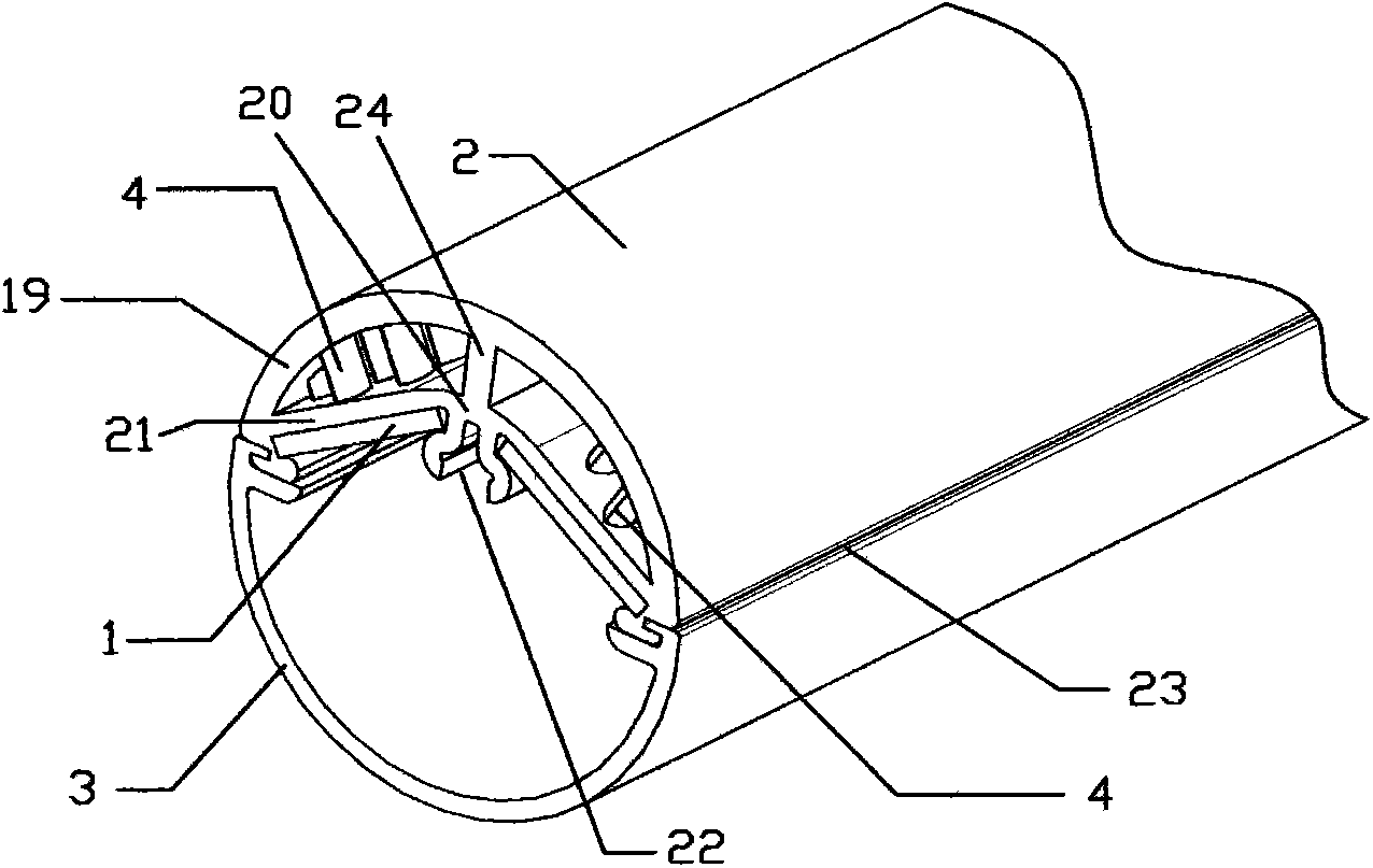
[0025] The LED light tube with self-adaptive fan cooling includes two LED light emitting circuit boards 1, a cooling frame 2 and a semi-tubular lampshade 3, and the angle between the two LED light emitting circuit boards 1 is 120° to 160°. The heat sink 2 includes an arc structure 19, the lower end of the arc structure 19 is connected with a herringbone structure 20, and the partition 24 at the upper end of the middle of the herringbone structure 20 divides the inner cavity of the heat sink 2 into two parts, the left and right, and the two sides of the herringbone structure 20 It is a slope partition 21; the upper surfaces of the two LED light-emitting circuit boards 1 are respectively attached to the lower surfaces of the two slope partitions 21; the lower end of the middle part of the herringbone structure 20 is provided with a threaded groove 22; A groove 23 is respectively provided under the end; the threaded groove 22 is used for threaded connection with the cover pin 5; t...

Embodiment 2

[0032] Such as Figure 9 As shown, the difference between this embodiment and Embodiment 1 is that a one-way exhaust window 9 is fixed at each exhaust hole 7; 10 components; two double-pole double-throw switches 16 are also fixed on the heat dissipation frame 2; the double-pole double-throw switch 16 can be fixed on the top of the heat dissipation frame 2; Towards.

[0033] When the present invention is installed on the vertical wall, the double pole double throw switch 16 of top cooling fan 8 is toggled to the exhaust position, and the double pole double throw switch 16 of bottom cooling fan 8 is toggled to the intake state. The radiating fan 8 positioned at the bottom blows toward the top like this, and the hot air is blown to the top of the inside of the cooling frame 2; discharged to the outside. When the cooling fan 8 at the lower part rotates in reverse, the one-way exhaust window 9 at the lower part forms a negative pressure in the cooling frame 2, and the blades 10 ...


PUM


Abstract

The invention discloses an adaptive fan-cooled LED lamp tube and relates to the technical field of non-portable indoor lighting sets. The adaptive fan-cooled LED lamp tube comprises two LED light-emitting circuit boards, a radiating rack and a semi-tubular lampshade; the two LED light-emitting circuit boards have an included angle of 120-160 degrees and are symmetrically attached to the lower surface of the radiating rack; radiating rods are vertically distributed on the left and right sides of an inner cavity of the radiating rack; the cross section of the radiating rods is in a streamline shape in the length-wise direction of the radiating rack; seal cap plugs of the LED light-emitting circuit boards are fixed to both ends of the radiating rack; each seal cap plug is provided with an air inlet; the radiating rack and the semi-tubular lampshade are connected in an inserted manner and are fixed through the seal cap plugs at two ends; the top center of the radiating rack is radially provided with at least one air outlet; a cooling fan is mounted in each air outlet. The adaptive fan-cooled LED lamp tube has the advantages of insufficiency in ventilation and good cooling effect.

Description

technical field [0001] The invention relates to the technical field of non-portable indoor lighting fixtures. Background technique [0002] Most of the existing LED tubes on the market adopt a passive heat dissipation method, that is, the LED light-emitting circuit board is attached to a heat-dissipating aluminum plate, and some high-power LED tubes that require high heat dissipation often use a cooling fan to actively dissipate heat from the heat-dissipating aluminum plate. However, the LED tubes currently on the market have not specifically optimized the shape of the heat sink on the surface of the heat dissipation aluminum plate and how to cooperate with the heat dissipation fan, so in fact, further research and improvement can be carried out on these two aspects. Contents of the invention [0003] The technical problem to be solved by the present invention is to provide an LED lamp tube with sufficient air circulation and good heat dissipation effect for heat dissipati...

Claims


Application Information

Patent Timeline
Patent Type & Authority Applications(China)
IPC IPC(8): F21S2/00F21V29/02F21Y101/02F21K9/27F21Y115/10
Inventor 陆亚丽
Owner 宁波丽安电子有限公司
Why Eureka
Try Eureka