
A method for measuring anchorage performance

An anchoring performance and bolt technology, which is applied in the direction of applying stable tension/pressure to test the strength of materials, can solve the problems of not being able to obtain the displacement curve and the indentation amount, etc., to improve scientific rationality, simple measurement, The effect of high measurement accuracy

Active Publication Date: 2016-08-24
CCTEG COAL MINING RES INST
View PDF5 Cites 0 Cited by
  • Summary
  • Abstract
  • Description
  • Claims
  • Application Information

AI Technical Summary

Problems solved by technology

At present, in bolt support engineering, there is no simple and easy anchoring performance testing device. Usually, the pulling force of the anchor is measured, or the detection data is read manually to calculate the anchoring performance.
The technical specification for bolt support in coal roadway stipulates that the pull-out test is mainly carried out by loading the bolt evenly and step by step until the bolt slides or the rod body is damaged. It is loaded by one person and recorded by one person. Only the sliding or breaking of the bolt can be measured. Pulling force, the indentation amount of the supporting plate and other surface protection structures of the anchor rod in the surrounding rock cannot be obtained, nor can the drawing force and the displacement curve between the anchor rod be obtained at each mechanical stage

Method used


Image

  • A method for measuring anchorage performance
  • A method for measuring anchorage performance

Examples


Embodiment Construction

[0023] The present invention will be further described in detail below in conjunction with the accompanying drawings, so that those skilled in the art can implement it with reference to the description.

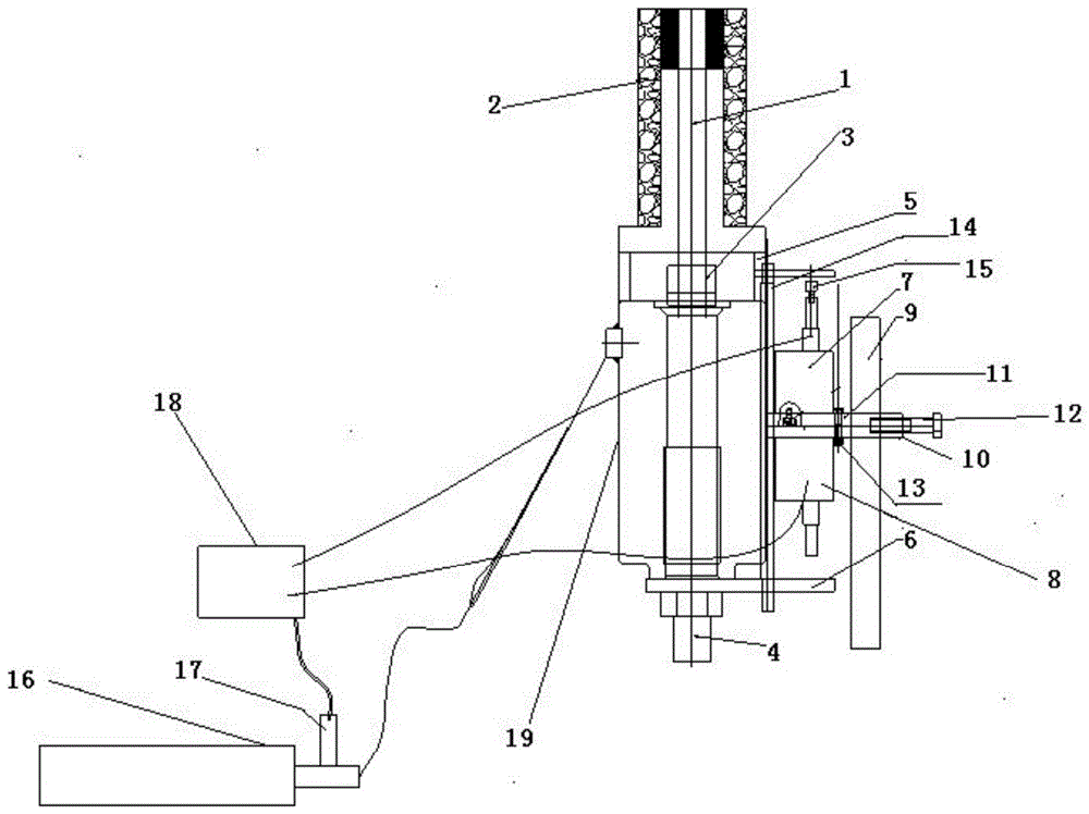
[0024] Such as figure 1 Shown, the present invention provides a kind of method for measuring anchor performance, comprises the following steps:

[0025] Step 1, a bolt is anchored on the surrounding rock of the coal and rock mass roadway, and the force applying device in the anchorage performance testing device is affixed to the bolt for applying a pulling force to the bolt;

[0026] Step 2: Set the detection device in the anchoring performance testing device on one side of the force applying device, the detection device includes a supporting first rod body, measures the displacement and is fixed on the first rod body The first displacement sensor and the second displacement sensor, the first rod body is arranged in such a way that its longitudinal axis is parallel to the lo...


PUM


Abstract

The invention discloses a method for measuring a property of an anchoring. The method comprises the following steps of carrying out anchoring on an anchor rod at a surrounding rock, fixedly arranging a force applying device on the anchor rod, enabling a detecting device to arrange on one side of the force applying device, wherein the detecting device comprises a first rod body, a first displacement sensor and a second displacement sensor, the vertical axis of first rod body is parallel to that of the anchor rod, one end of the first displacement sensor is fixedly connected to the first rod body, the other end of the first displacement sensor is connected to the anchor rod, one end of a second sensor is fixedly connected to the first rod body, and the other end of the second sensor is connected to an anchor rod supporting plate; gradually applying pulling force on the anchor rod through the force applying device, and detecting and recording the size of the pulling force applied by the force applying device through a pressure sensor; and detecting and recording the displacement generated by the force applying device through being relative to the first rod body under a gradually applying pulling force action by using the first displacement sensor, and detecting and recording the pressing displacement of the anchor rod supporting plate through being relative to the first rod body to the surrounding rock by using the second displacement sensor. The method provided by the invention has the advantages that the operation is simple, the accuracy is high, and the automation degree is high.

Description

technical field [0001] The invention belongs to the technical field of bolt support for rock masses such as coal mines, metal mines or tunnels, and particularly relates to a method for measuring anchor performance. Background technique [0002] Prestressed bolts have been widely used in underground engineering in many fields such as water conservancy, mining, transportation, and construction. The purpose of the bolt pullout test is to determine the anchorability of the surrounding rock of the roadway, and to evaluate the performance of the bolt, resin, and surrounding rock anchoring system and the anchoring force of the bolt. The anchorability test of surrounding rock is the basic work for roadway bolt support design, and it is also the basis for judging whether bolt support can be used for soft rock roadway or high gas coal seam roadway for gas drainage, especially for high prestress strength The bolt support system is the key to the success of the anchor support of the su...

Claims


Application Information

Patent Timeline
Patent Type & Authority Patents(China)
IPC IPC(8): G01N3/08
Inventor 林健吴志刚
Owner CCTEG COAL MINING RES INST
Learn More