Auxiliary device for measuring detonation velocity of emulsified explosive in blast hole

An auxiliary device, the technology of emulsion explosives, which is applied in the direction of using a device for measuring the time required to move a certain distance, can solve the problems of unable to measure the detonation velocity of emulsion explosives and is expensive, and achieve the effect of simple structure, low price, and high price

Active Publication Date: 2014-09-10
CHINA GEZHOUBA GRP YIPULI CO LTD
View PDF6 Cites 3 Cited by
  • Summary
  • Abstract
  • Description
  • Claims
  • Application Information

AI Technical Summary

Problems solved by technology

The above two methods can measure the detonation velocity of emulsion explosives under known constraints such as paper cylinder, plastic cylinder or steel cylinder, and use this constraint condition to simulate the detonation velocity in the blasthole. There is a significant difference in the detonation velocity of the emulsion explosive, and these two methods cannot measure the real detonation velocity of the emulsion explosive in the blast hole
[0003] The existing in-hole continuous detonation velocity meter can measure the in-hole detonation velocity, but due to its high price (about one hundred thousand yuan), it has not been widely used in the civil explosion industry

Method used


Image

  • Auxiliary device for measuring detonation velocity of emulsified explosive in blast hole
  • Auxiliary device for measuring detonation velocity of emulsified explosive in blast hole
  • Auxiliary device for measuring detonation velocity of emulsified explosive in blast hole

Examples


Embodiment Construction

[0014] Below in conjunction with accompanying drawing and embodiment the present invention will be further described:

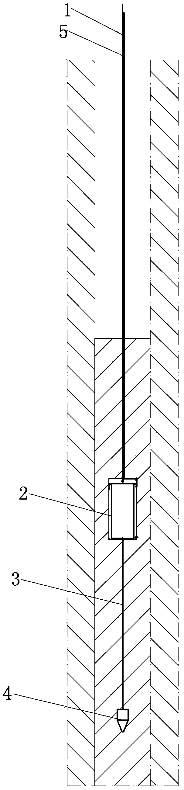
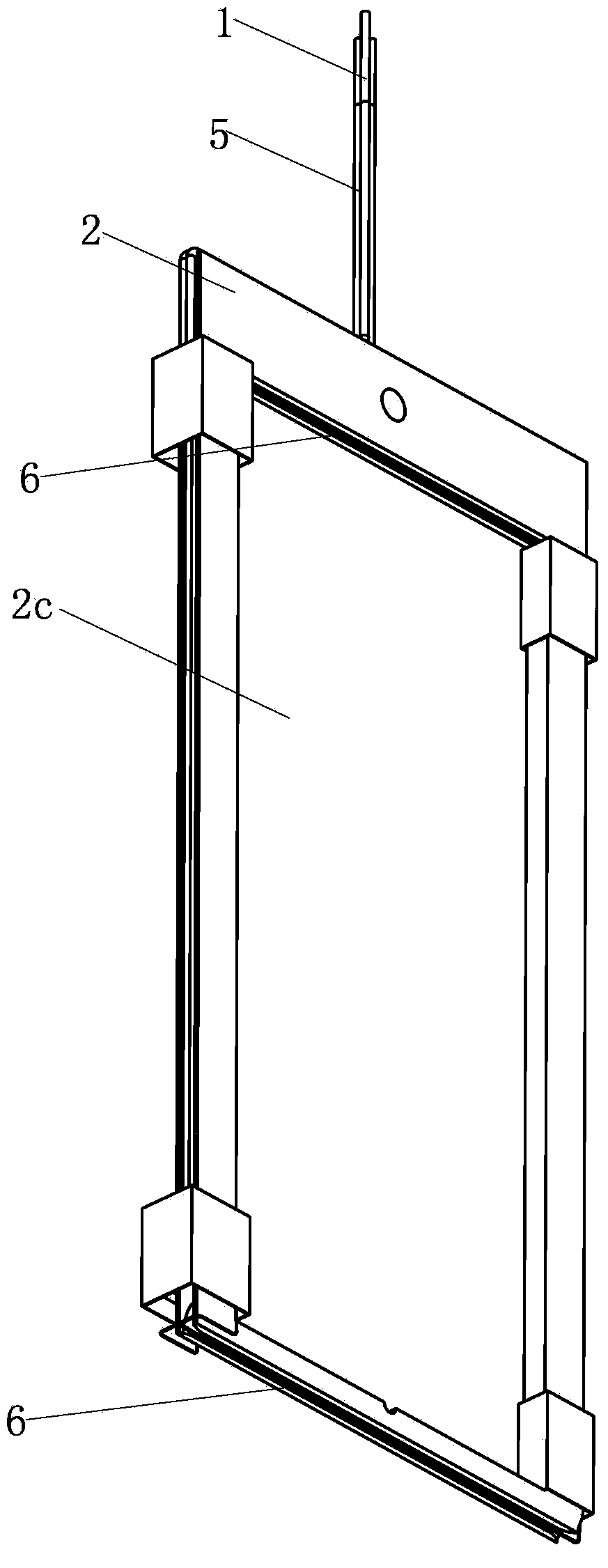
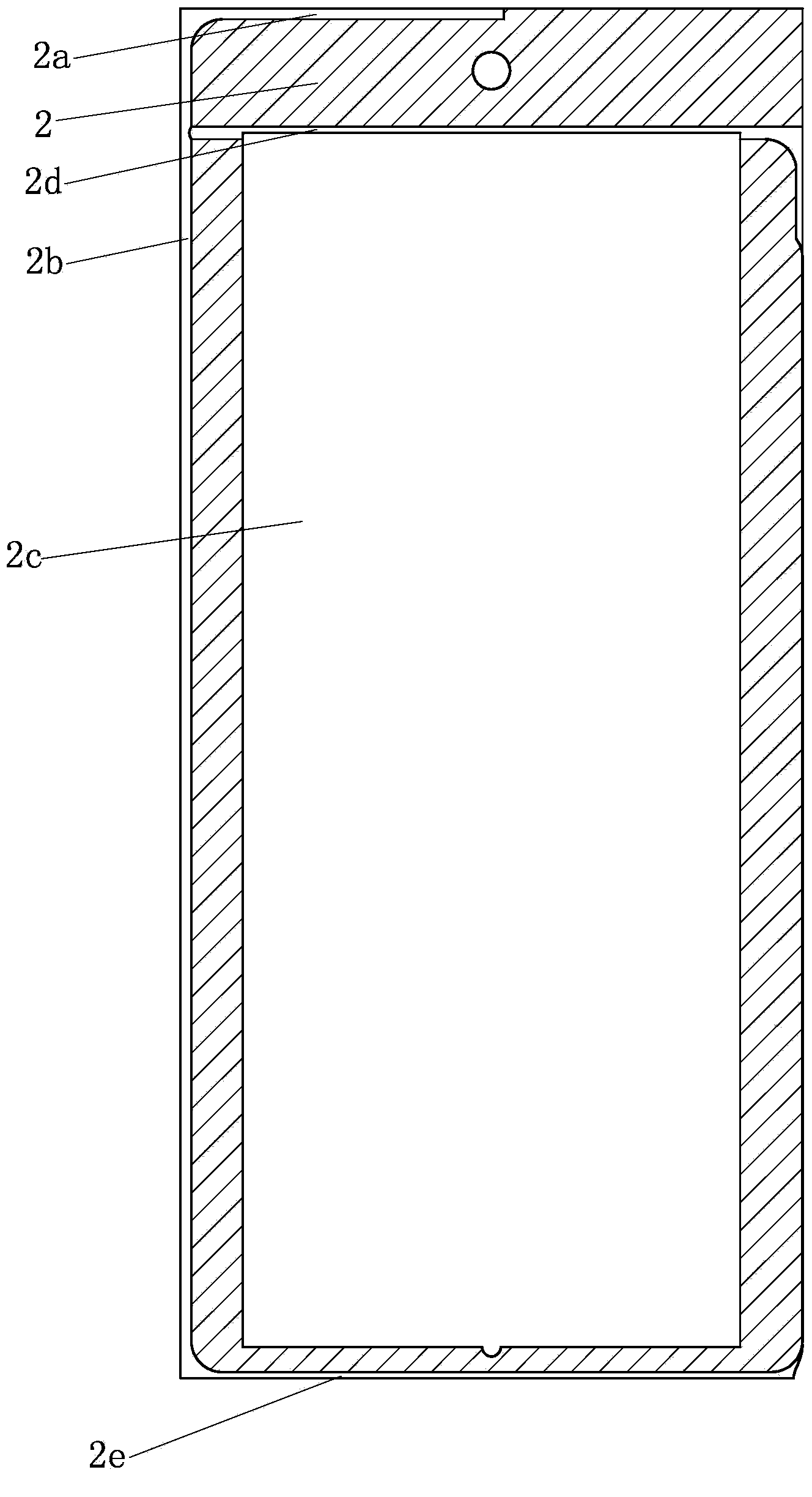
[0015] Such as figure 1 , 2 As shown in and 3, an auxiliary device for measuring the detonation velocity of emulsion explosives in a blasthole mainly consists of a fixed wire 1, a target wire plate 2, a pull wire 3, a weight 4, a wire 5 and an enamelled copper wire 6, wherein The upper end of the fixed line 1 is suspended in the air, and the suspended end of the fixed line 1 is fixed at the hole of the blasthole before the measurement, and the lower end of the fixed line 1 is fixed with the upper part of the target line plate 2, thereby fixing the auxiliary device in the blasthole. The bottom of the target line board 2 is hung with a weight 4 through a stay wire 3, the material of the weight 4 can be iron or stone, etc., and the fixed line 1 and the stay wire 3 are all located In the center, it can ensure that the target line board 2 does not deflect, and e...


PUM


Abstract

The invention discloses an auxiliary device for measuring a detonation velocity of an emulsified explosive in a blast hole. The lower end of a fixed line is fixed on the upper part of a target line plate, and a weight is suspended on the lower part of the target line plate by use of a pull line; a conductor is composed of four thin conductors, the tail ends of the four thin conductors are all connected with enameled copper wires, respectively, two enameled copper wires are twined and then clamped in an upper target line groove, and the tail ends of the two enameled copper wires are covered with waterproof adhesive tapes; the other two enameled copper wires are twined and then clamped in a lower target line groove, and the tail ends of the two enameled copper wires are covered with waterproof adhesive tapes. Heat generated during blasting is capable of connecting the upper two enameled copper wires and the lower two enameled copper wires, and the corresponding thin conductors successively; the ratio of the distance between the upper target line groove and the lower target line groove to the time difference between connection signals is calculated to obtain the detonation velocity of the emulsified explosive in the blast hole, and in this way, the defects of an electrometric method and a detonating cord method both failing in accurately measuring the detonation velocity in the blast hole are overcome; furthermore, as the auxiliary device is composed of cheap common components, the manufacturing cost of the auxiliary device is relatively low.

Description

technical field [0001] The invention belongs to the field of detonation velocity measurement, and in particular relates to an auxiliary device for measuring the detonation velocity of emulsion explosives in a blast hole. Background technique [0002] Detonation velocity is an important parameter to reflect the performance of emulsion explosives. The existing testing methods mainly include electrical measurement method and detonating cord method. The above two methods can measure the detonation velocity of emulsion explosives under known constraints such as paper cylinder, plastic cylinder or steel cylinder, and use this constraint condition to simulate the detonation velocity in the blasthole. There is a significant difference in the detonation velocity of the emulsion explosive, and these two methods cannot measure the real detonation velocity of the emulsion explosive in the blast hole. [0003] The existing in-hole continuous detonation velocity meter can measure the in-...

Claims


Application Information

Patent Timeline
Patent Type & Authority Applications(China)
IPC IPC(8): G01P3/66
Inventor 陈曦周桂松朱根华刘小钧李名松
Owner CHINA GEZHOUBA GRP YIPULI CO LTD
Why Eureka
Try Eureka