Compact disc barrel
A technology for optical discs and optical disc holders, applied in the field of optical disc barrels, can solve the problems of disc falling off, troublesome operation, and instability, and achieve the effects of not easy to accumulate dust or damage, easy to operate, and not easy to fall off
- Summary
- Abstract
- Description
- Claims
- Application Information
AI Technical Summary
Problems solved by technology
Method used
Image

Examples
Embodiment Construction
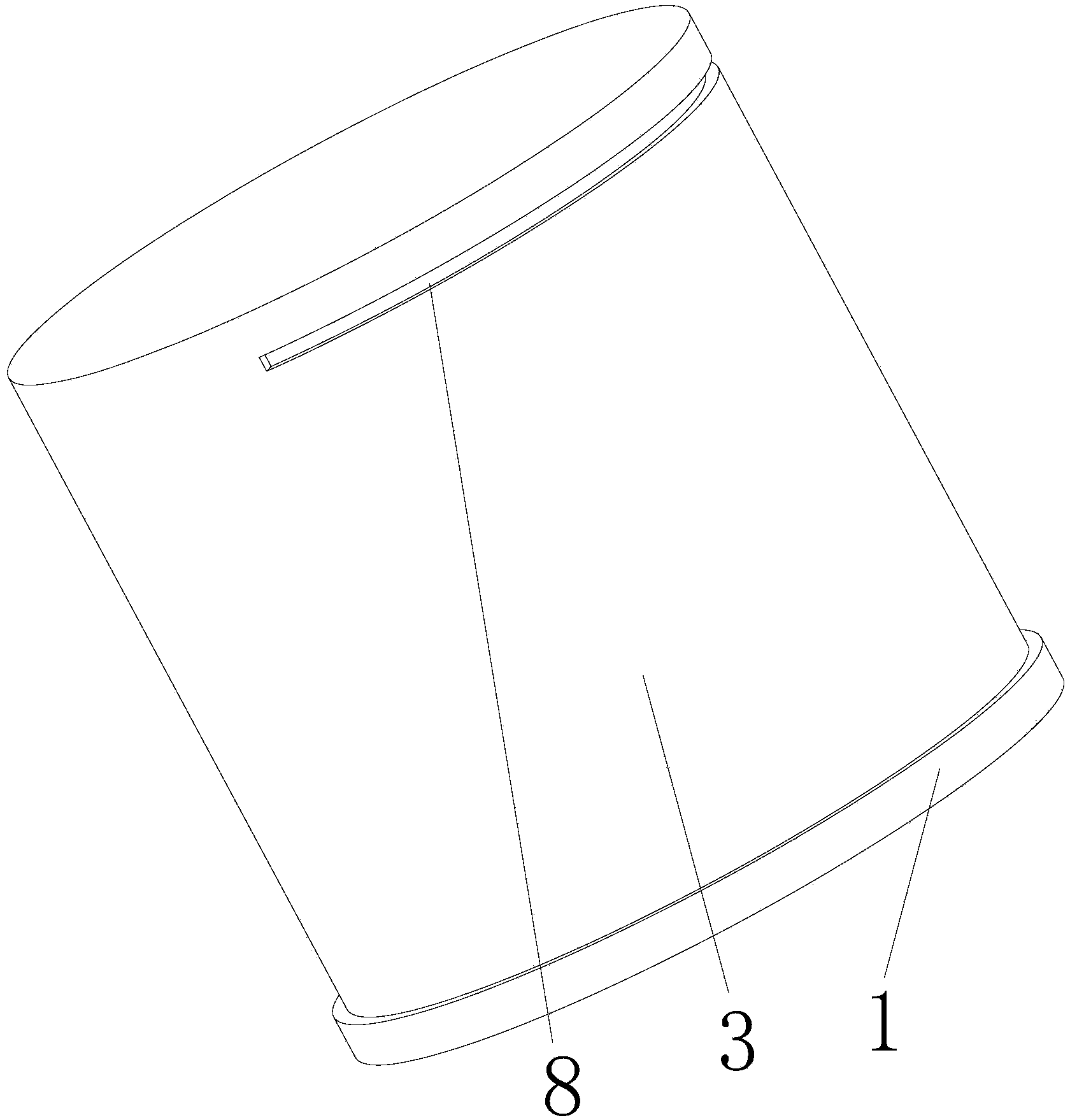
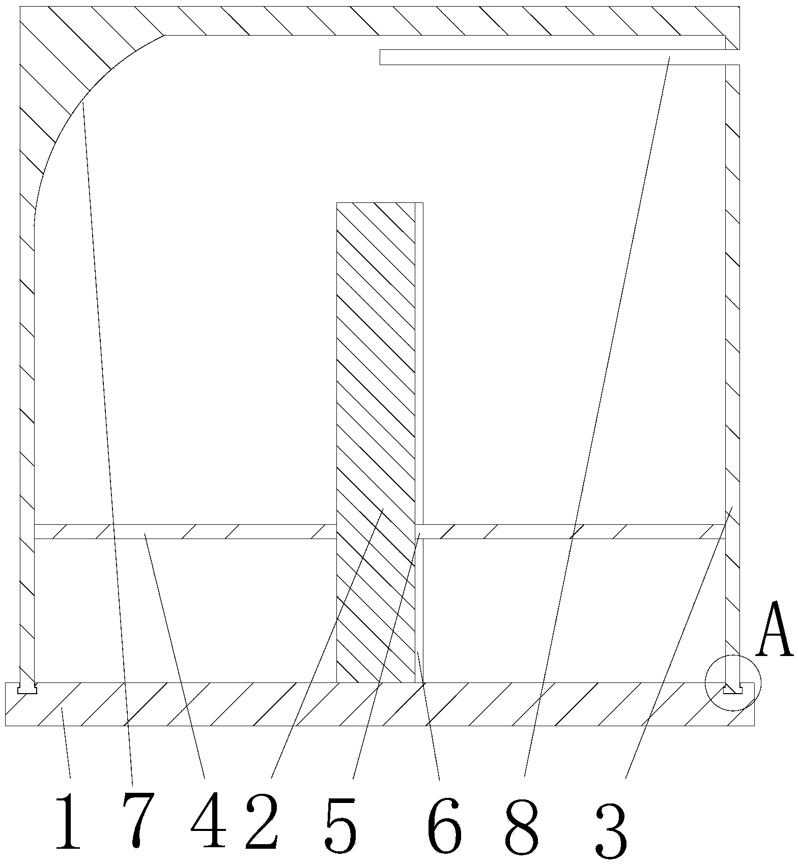
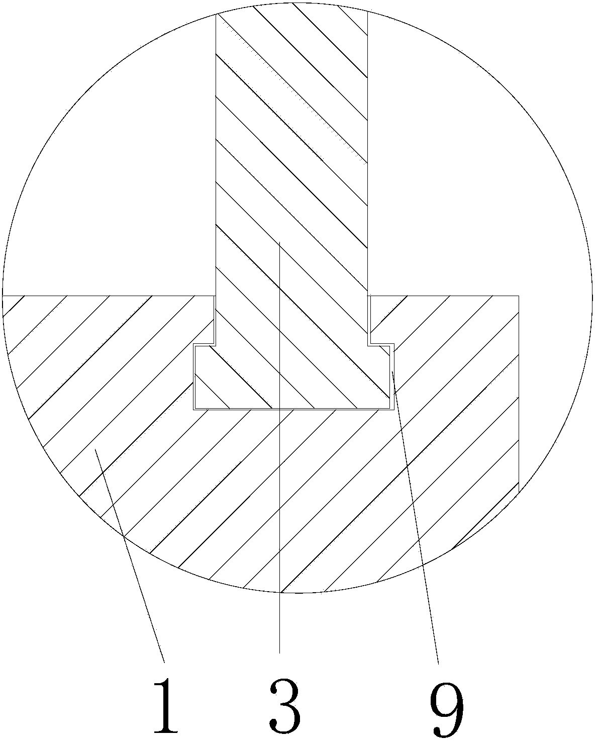
[0013] Figure 1-3 One embodiment of the invention is shown.
[0014] A disc drum, comprising a cylindrical base 1, the base 1 is provided with a fixed column 2 for axially positioning the disc through the disc hole, and a shield 3 with an open end of the cylinder, and the open end of the guard 3 is provided with On the base 1, the shield 3, the base 1, and the fixed column 2 are coaxial, the shield 3 can rotate around the axis of the shield 3 on the base 1, and the inner wall of the shield 3 is provided with threads (not shown in the figure), The fixed column 2 is covered with a CD tray 4, which can slide up and down along the fixed column 2, and the CD tray 4 is provided with a positioning key 5 fixed with the CD tray 4, and the fixed column 2 is provided with a positioning groove 6, and the positioning groove 6 is fixed along the The column 2 is axially arranged on the side wall of the fixed column 2, and the positioning key 5 is embedded in the positioning groove 6. Thre...
PUM
 Abstract
Description
Claims
Application Information
 - Generate Ideas
- Intellectual Property
- Life Sciences
- Materials
- Tech Scout
- Unparalleled Data Quality
- Higher Quality Content
- 60% Fewer Hallucinations
Browse by: Latest US Patents, China's latest patents, Technical Efficacy Thesaurus, Application Domain, Technology Topic, Popular Technical Reports.
© 2025 PatSnap. All rights reserved.Legal|Privacy policy|Modern Slavery Act Transparency Statement|Sitemap|About US| Contact US: help@patsnap.com