
Multiplex circuit for digital signals

A technology of multiplexing circuits and digital signals, which is applied in the direction of logic circuit coupling/interface, logic circuit connection/interface layout, etc., using field effect transistors, can solve the problems that cannot meet the requirements, the circuit cannot be multiplexed, etc., and achieve effective use Sex, the effect of satisfying compatibility

Active Publication Date: 2014-09-10
SHANGHAI HUAXING DIGITAL TECH
View PDF4 Cites 1 Cited by
  • Summary
  • Abstract
  • Description
  • Claims
  • Application Information

AI Technical Summary

Problems solved by technology

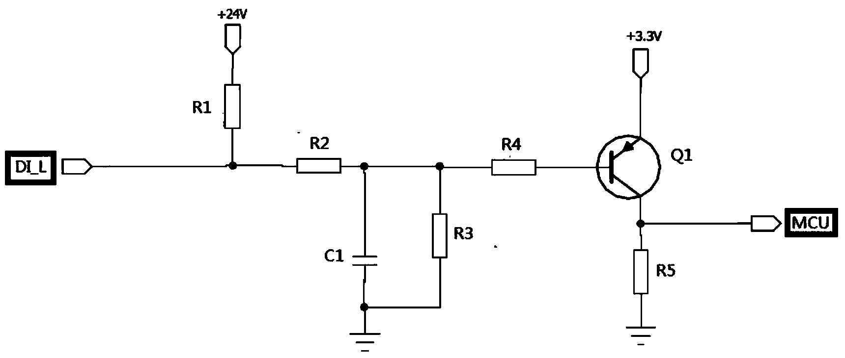
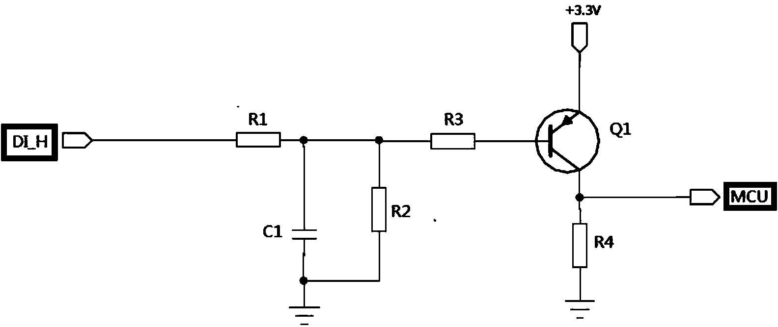
However, in this way, the compatibility of the product with respect to the number of DI_L / H requirements and the reusability of the port circuit due to limited port resources cannot meet the requirements, and the general DI_L / H circuit such as Figure 1a and Figure 1b As shown in the circuit shown in the figure, when the DI_L input is at an effective low level, the MCU input is at a high level after circuit conversion; when the DI_H input is at an effective high level, after the circuit conversion, the MCU input is at a low level, The two circuits cannot be multiplexed

Method used


Image

  • Multiplex circuit for digital signals
  • Multiplex circuit for digital signals
  • Multiplex circuit for digital signals

Examples


Embodiment Construction

[0023] The following will clearly and completely describe the technical solutions in the embodiments of the present invention with reference to the accompanying drawings in the embodiments of the present invention. Obviously, the described embodiments are only some, not all, embodiments of the present invention. Based on the embodiments of the present invention, all other embodiments obtained by persons of ordinary skill in the art without creative efforts fall within the protection scope of the present invention.

[0024] It should be noted that, in the case of no conflict, the embodiments of the present invention and the features in the embodiments can be combined with each other.

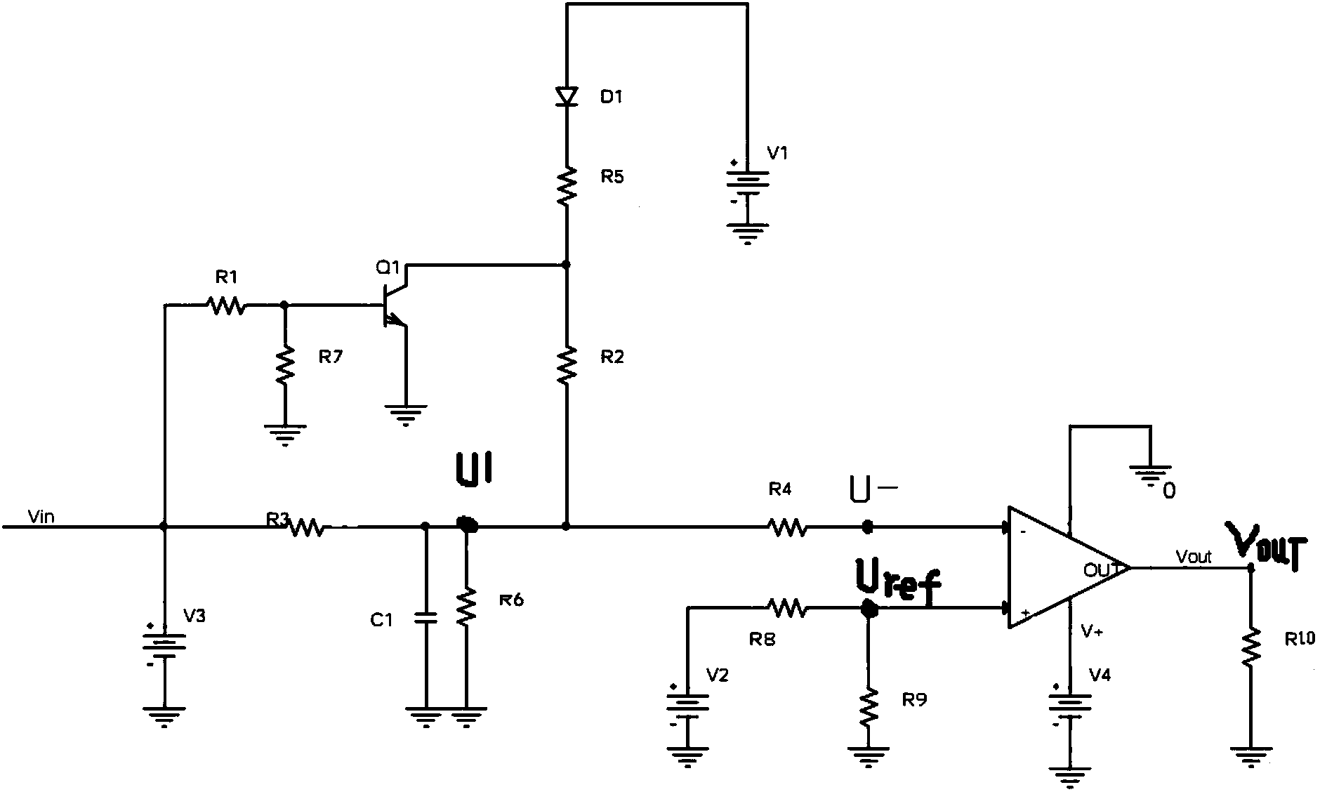
[0025] see figure 2 As shown, the digital signal multiplexing circuit of the present invention is set between the input terminal Vin and the output terminal Vout, specifically including the first power supply V1, the second power supply V2, the third power supply V3, the fourth power supply V4, ...


PUM

PropertyMeasurementUnit
First resistoraaaaaaaaaa
Second resistoraaaaaaaaaa
Third resistoraaaaaaaaaa

Abstract

The invention discloses a multiplex circuit for digital signals. A collector of an audion, a fifth resistor, a diode and a first power supply are sequentially connected, a base of the audion is grounded through a seventh resistor and is connected with an input end through a first resistor and the collector of the audion is connected with a fourth resistor through a second resistor; the input end is connected with an inverted input end of a comparer through a third resistor and a fourth resistor, the third resistor and the fourth resistor are respectively grounded through a capacitor and are grounded through a sixth resistor, the input end is connected with a third power supply, an in-phase input end of the comparer, an eighth resistor and a second power supply are sequentially connected; the in-phase input end of the comparer is grounded through a ninth resistor, the power supply end of the comparer is connected with a fourth power supply, and an output end is grounded through a tenth resistor. According to the multiplex circuit, the different quantities of DI-L / H demanded by customers can be met, and the compatibility of products can be met; furthermore, for the limited plug port resources of product, the DI-L / H multiplex circuit can meet the use effectiveness of ports better.

Description

technical field [0001] The invention relates to circuit technology, in particular to a digital signal multiplexing circuit. Background technique [0002] In vehicle controllers or testing instruments of automobiles and construction machinery, a large number of sensor signals need to be input, and most of the sensor signals are digital signals, so it is necessary to convert the digital signals into TTL levels that the control chip can receive, so the The application of conversion circuits for converting digital input signals to TTL levels has become very common. [0003] The current input digital signal is generally in two signal states of active low or active high, that is, DI_L / H. The general design is a conversion circuit for a low effective signal corresponding to a low effective signal, and a conversion circuit for a high effective signal corresponding to a high effective signal. However, in this way, the compatibility of the product with respect to the number of DI_L / H...

Claims


Application Information

Patent Timeline
IPC IPC(8): H03K19/0185
Inventor 邓武仓李强杨国勋
Owner SHANGHAI HUAXING DIGITAL TECH
Learn More