Cutting machine

A cutting machine and cutting edge technology, which is applied to sawing equipment, metal sawing equipment, sawing machine devices, etc., can solve the problems of larger size of the cutting machine, increased cost, complex structure, etc., so as to suppress the increase in cost and expand cutting. Width, the effect of ensuring cutting ability

Inactive Publication Date: 2014-09-10
MAKITA CORP
View PDF7 Cites 1 Cited by
  • Summary
  • Abstract
  • Description
  • Claims
  • Application Information

AI Technical Summary

Problems solved by technology

[0006] However, enabling the main body to slide forward and backward not only increases the size of the entire cutting machine, but also complicates its structure, leading to an increase in cost

Method used


Image

  • Cutting machine
  • Cutting machine
  • Cutting machine

Examples


Embodiment Construction

[0028] Next, specific embodiments of the present invention will be described with reference to the drawings.

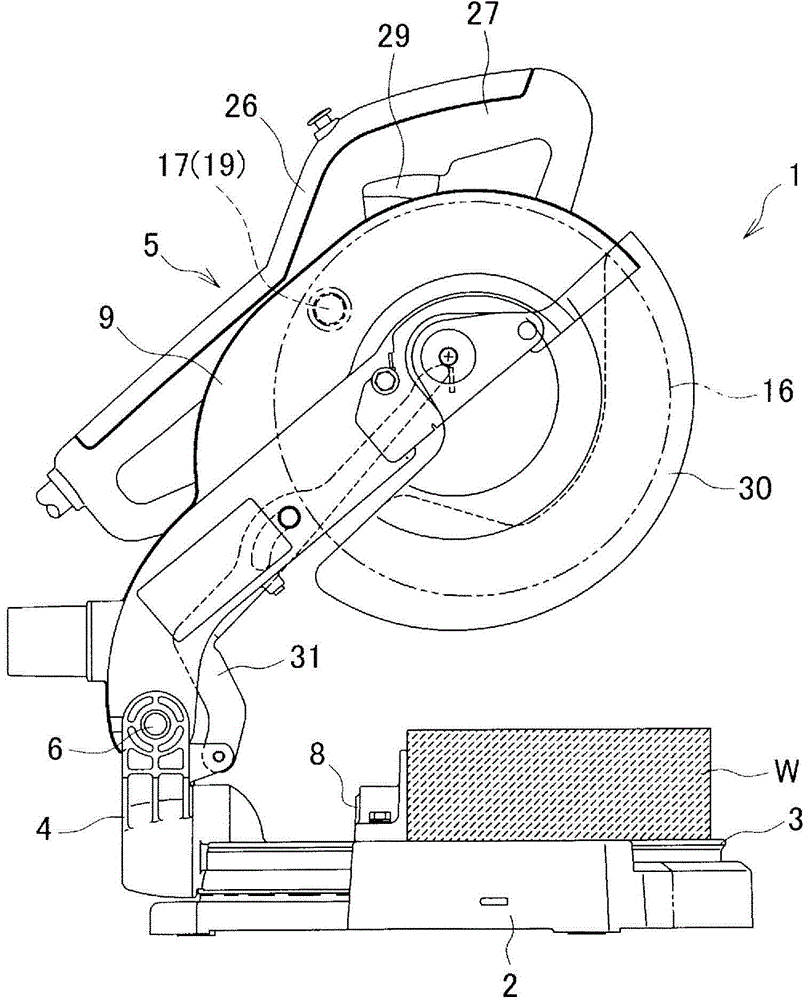
[0029] figure 1 It is a left side view of a desktop circular saw as an example of a cutting machine. In the desktop circular saw 1, a turntable 3 capable of horizontal rotation is placed on a base 2. The height of the upper surface of the turntable 3 is the same as that of the base 2. The same height of the upper surface, at the rear end of turntable 3 (with figure 1 The right side of the paper in the middle is the front) erectly provided with a support arm 4 that can rotate around the axis in the front-rear direction, and at the upper end of the support arm 4, a rotatable main body 5 is installed through a fulcrum 6 in the left-right direction. However, in the normal state due to being arranged on the torsion spring 7 on the fulcrum 6 (refer to Figure 4 ) of the force, the main body 5 is in the figure 1 upper limit position shown. 8 denotes a guide baffle, and t...


PUM


Abstract

To obtain high cutting ability, using a simple configuration capable of maintaining increased compactness and low cost. [Solution] A bench circular saw, wherein a unit (U) extending from a motor (12) to a saw blade (16) is separated, as a separate body, inside a main body (5), and the unit (U) is held inside the main body (5) so as to be swingable in the front-rear direction at the lower limit position of the main body (5). As a result, a wide cutting width can be obtained using a simple configuration whereby only the unit (U) is swung, without sliding the whole main body (5) in the front-rear direction.

Description

technical field [0001] The invention relates to a cutting machine such as a desktop circular saw. Background technique [0002] In a cutting machine such as a desktop circular saw machine, a main body capable of moving up and down is provided on a base on which a workpiece is placed. The main body has a cutting blade driven by a motor to rotate. The workpiece is cut (for example, Patent Document 1). [0003] The cutting capability of such a cutting machine (dimensions (cutting width) in the front-rear direction of the cuttable workpiece that can be cut) is determined by the diameter of the cutting blade. Therefore, as a cutting machine that can cut a workpiece with a large cutting width, For example, a cutting machine such as a sliding circular saw disclosed in Patent Document 2 is known in which the main body of the cutting machine can slide forward and backward. [0004] [Patent Document 1] Japanese Invention Patent Laid-Open Publication No. 8-332605 [0005] [Patent Do...

Claims


Application Information

Patent Timeline
Patent Type & Authority Applications(China)
IPC IPC(8): B23D45/04B23D47/02
CPCB23D45/042Y10T83/7697B23D45/044B27B5/188B23D47/02Y10T83/7693
Inventor 可儿利之
Owner MAKITA CORP
Why Eureka
Try Eureka