
Electric mattress and method for manufacturing same

A manufacturing method and technology of electrical steel, applied in the direction of manufacturing tools, circuits, electrical components, etc., can solve problems such as unfavorable environmental protection, difficulty in ensuring the iron loss characteristics of the final product, mechanical processing stability, and reliability of complex processes, etc. , to achieve the effect of improving the subdivision effect of the magnetic region

Active Publication Date: 2014-09-10
浦项股份有限公司
View PDF2 Cites 9 Cited by
  • Summary
  • Abstract
  • Description
  • Claims
  • Application Information

AI Technical Summary

Problems solved by technology

The etching method forms grooves on the surface of the steel sheet through an electrochemical corrosion reaction in an acidic solution, so it is difficult to control the shape of the groove (groove width, groove length), and due to the intermediate process of producing steel sheets (decarburization annealing , before high-temperature annealing) to form grooves, it is difficult to ensure the iron loss characteristics of the final product, because the use of acidic solution is not conducive to environmental protection, it has this disadvantage
[0008] Using the method of subdividing the permanent magnetic region of the roller, the protrusion shape is processed on the roller, and grooves with a certain width and length are formed on the surface of the steel sheet by applying pressure, and the steel sheet is annealed after the subdivision of the permanent magnetic region to make the groove The lower side of the groove is recrystallized to subdivide the magnetic domain, but it has the disadvantages of stability, reliability and complicated process of machining
[0009] The method of subdividing the permanent magnetic region by pulsed laser, forming grooves by evaporation, thereby inhibiting the formation of the melting zone, so it is difficult to ensure the improvement rate of iron loss before heat treatment (stress relief annealing, SRA), and after heat treatment by simple The groove can only maintain the subdivision effect of the magnetic area, but cannot handle the moving speed of the steel sheet at a high speed, which has this disadvantage

Method used

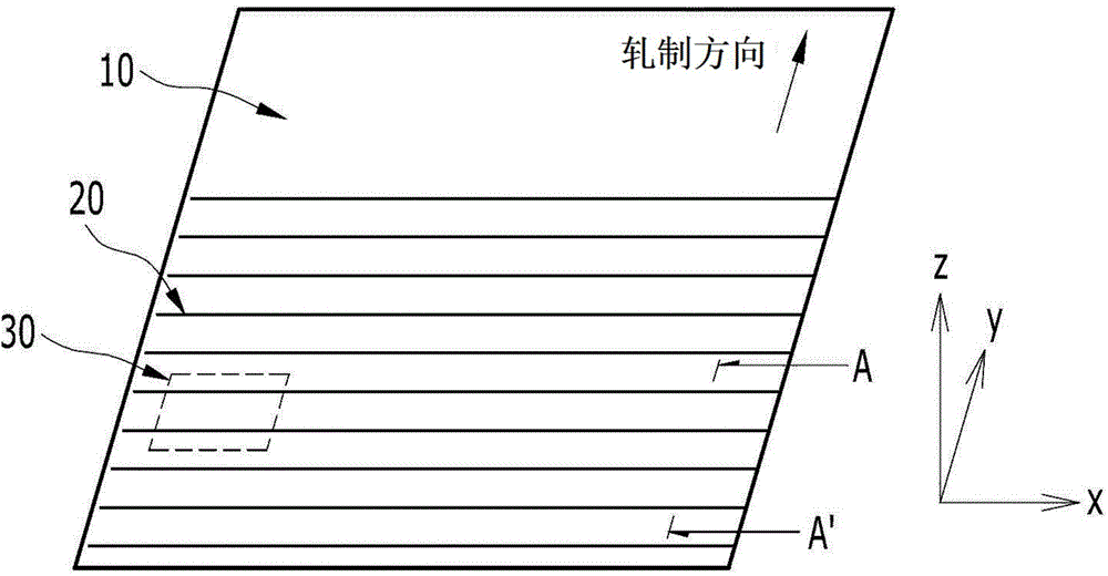
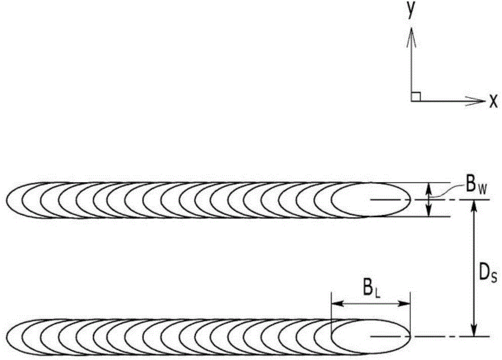
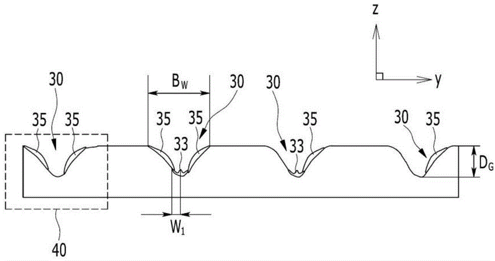

Image

  • Electric mattress and method for manufacturing same
  • Electric mattress and method for manufacturing same
  • Electric mattress and method for manufacturing same

Examples


Embodiment Construction

[0044]The advantages and features of the present invention and methods for realizing them will become more apparent with reference to the accompanying drawings and detailed embodiments described later. However, the present invention is not limited to the embodiments disclosed below, but can be implemented in various forms different from each other, but this embodiment will make the disclosure of the present invention more complete, and will make people with ordinary knowledge in the technical field to which the present invention belongs A more complete understanding of the scope of the invention. The scope of the present invention is defined only by the claims. The same reference numerals denote the same structural elements throughout the specification.

[0045] Next, an electrical steel sheet having grooves on the surface of the steel sheet for subdividing the magnetic domains will be described with reference to preferred embodiments of the present invention.

[0046] figu...


PUM

PropertyMeasurementUnit
depthaaaaaaaaaa

Abstract

Provided is a method for manufacturing an electric mattress. The method for manufacturing the electric mattress includes: a step of melting the surface of a steel plate by irradiating a laser beam to form a groove having first and second side surfaces and a bottom surface; and a step of air-blow or suction molding the steel plate byproduct formed on the first and second side surfaces and the bottom surface of the groove in the groove formation step to form an opening part through which at least one surface of the first and second side surfaces and the bottom surface is exposed.

Description

technical field [0001] The invention relates to an electrical steel, in particular to an orientation electrical steel which forms grooves by irradiating laser light on the surface of a steel sheet, thereby subdividing the magnetic regions of the steel sheet. Background technique [0002] Grain-oriented electrical steel is mostly used as the core material of electronic devices such as transformers. In order to reduce the power loss of electronic devices and improve efficiency, steel sheets with low iron loss and high magnetic flux density are required. [0003] Generally, grain-oriented electrical steel refers to a material with a crystal texture (also known as "Gauss texture") oriented toward the rolling direction {110}<001> after hot rolling, cold rolling, and annealing. [0004] In this grain-oriented electrical steel, the {110}<001> orientation is the direction in which iron is easily magnetized. The higher the orientation degree, the better the magnetic chara...

Claims


Application Information

Patent Timeline
Patent Type & Authority Applications(China)
IPC IPC(8): C21D8/12
CPCH01F3/02C21D2201/05B23K26/0081B23K26/0736C21D8/1288B23K26/0643C21D8/1294B23K26/0084B23K26/0009H01B1/02B23K26/1405H01B5/002B23K26/354B23K26/355C21D8/12
Inventor 权五烈李原杰韩赞熙朴炫哲
Owner 浦项股份有限公司
Learn More