
A flame detection device

A flame detection and detector technology, applied in the field of safety monitoring devices, can solve problems affecting the detection accuracy of flame detectors and unfavorable detection performance of flame detectors, achieve good distance adjustment performance, good angle adjustment performance, and avoid thermal resistance changes big effect

Active Publication Date: 2016-05-11
SICHUAN TIANWEI ELECTRONICS
View PDF13 Cites 0 Cited by
  • Summary
  • Abstract
  • Description
  • Claims
  • Application Information

AI Technical Summary

Problems solved by technology

[0004] In view of the above-mentioned prior art, during installation or use, the fixed error of the fixed point and the position change of the fixed point during use will affect the detection accuracy of the flame detector, which is not conducive to ensuring the stable detection performance of the flame detector , the invention provides a flame detection device

Method used


Image

  • A flame detection device

Examples


Embodiment 1

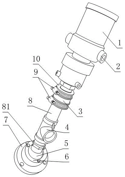
[0025] Such as figure 1 , a flame detection device, comprising a detector body 1, a cooling part and a fixing part, the detector body 1 includes a casing, the casing is in a cylindrical structure, and the two ends of the cooling part are respectively connected to the casing of the detector body 1 On the open end and the fixed part;

[0026] The cooling part includes two air ducts 8 connected in series and an adjustment part for adjusting the length of the cooling part. The barrel 3 is provided with through holes running through its two ends, and one end of the two air ducts 8 extends into the tightening barrel 3 from different ends of the through holes respectively, and the two air ducts 8 pass through a hoop 9 and the tightening barrel respectively. 3 fixedly connected, any position on the air duct 8 is also provided with an air inlet 4;

[0027] The fixed part includes a mounting plate 7, a rolling ball 5 and a ball seat 6, the ball seat 6 is provided with a spherical cavi...

Embodiment 2

[0031] The present embodiment is further limited on the basis of embodiment 1, as figure 1 , in order to make the cooling part in the present invention have a longer length adjustment range, the air pipes 8 at both ends of the clamping tube 3 are circular pipes, and the diameters of the two air pipes 8 are different in diameter, and the air pipe with a larger diameter 8 are set on the air duct 8 with smaller diameter. At the same time, the contact between the inner and outer sides of the two air ducts 8 is also beneficial to the rigidity of the cooling part and its ability to support the detector body 1 .

[0032] In order to make the two air pipes 8 have a compact fit relationship, which is beneficial to ensure the position of the detector body 1 relative to the monitoring point, and is beneficial to the detection effect of the present invention, the distance between the two air pipes 8 in the cooling part is not greater than 0.3mm.

[0033] In this embodiment, in order to f...

Embodiment 3

[0035] The present embodiment is further limited on the basis of embodiment 1, as figure 1, in order to prevent the formation of cooling wind dead angle on the housing of the detector body 1, the number of the air outlets 2 is multiple. That is, a plurality of air outlets 2 are set on the outer casing of the detector body 1, so that there is flowing cooling air at each position in the outer casing. Furthermore, in places where forced cooling is required, more dense outlets can be arranged on the outer casing. Air outlet 2 or outlet 2 with larger outlet.


PUM


Abstract

The invention discloses a flame detection device. The flame detection device comprises a detector body, a cooling part and a fixing part. The detector body comprises a shell. The cooling part comprises two air pipes connected in series and an adjusting part, the adjusting part comprises a banding cylinder and two hoops arranged on the banding cylinder in a sleeved mode, a through hole penetrating through the two ends of the banding cylinder is formed in the banding cylinder, and an air inlet is further formed in any position of each air pipe. The fixing part comprises an installing plate, a rolling ball and a ball seat, and a spherical cavity is formed in the ball seat. An air outlet is further formed in the shell of the detector body. The flame detection device is simple in structure; the detector body has good angle and spacing adjustment performance relative to a monitoring point, so that the angle and spacing adjustment in the installing and using process of the flame detection device can be facilitated; meanwhile, the structure of the flame detection device is favorable for guaranteeing the long-term sensitivity and the excellent cooling effect of the flame detection device.

Description

technical field [0001] The invention relates to a safety monitoring device for supervising flame conditions, in particular to a flame detection device. Background technique [0002] At present, there are gaseous or solid combustibles in chemical plants, oil refineries, substations, industrial warehouses, and even common diesel generator rooms used as emergency power sources, people's living environments, whether it is numerous industrial control equipment or complex Living environment, if the fire is strictly monitored in these occasions, it will provide great protection for property protection and people's life safety. [0003] Flame detector, also known as photosensitive fire detector, is a fire detector used to respond to the light characteristics of fire, that is, to detect the light intensity of flame burning and the flicker frequency of flame. In the prior art, flame detection devices are generally in Infrared detectors are packaged in aluminum or plastic shells. Flam...

Claims


Application Information

Patent Timeline
Patent Type & Authority Patents(China)
IPC IPC(8): G01J1/04
Inventor 余盛明黄成国汪小婷杨德志
Owner SICHUAN TIANWEI ELECTRONICS
Learn More