Eureka AIR delivers breakthrough ideas for toughest innovation challenges, trusted by R&D personnel around the world.

Lens for head-mounted display device and head-mounted device

A display device and lens technology, applied in optical components, optics, instruments, etc., can solve the problems of high cost and high system heat generation, and achieve the effects of stable production performance, LCA aberration correction, and easy molding.

Active Publication Date: 2016-09-07
GOERTEK OPTICAL TECH CO LTD
View PDF4 Cites 0 Cited by
  • Summary
  • Abstract
  • Description
  • Claims
  • Application Information

AI Technical Summary

Problems solved by technology

[0004] In order to solve the problems that the existing lens used for the head-mounted display device needs to preprocess the image first, the system generates high heat, and the cost is high, the present invention proposes a lens for the head-mounted display device and the head-mounted device, and adopts the following The technical solution is realized:

Method used


Image

  • Lens for head-mounted display device and head-mounted device
  • Lens for head-mounted display device and head-mounted device
  • Lens for head-mounted display device and head-mounted device

Examples


Embodiment 1

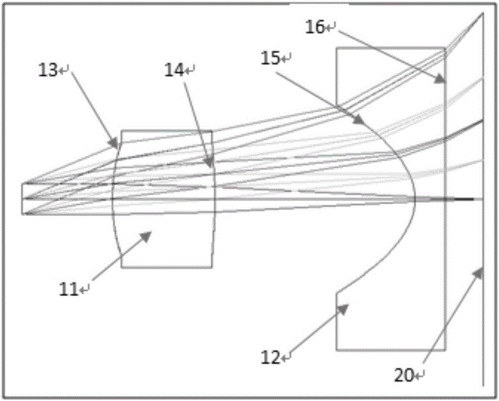
[0030] refer to figure 2 , the present invention is used for a lens for a head-mounted display device, including a biconvex lens 11 and a plano-concave cylindrical mirror 12 arranged side by side; Far away from the human eye side; the biconvex lens 11 includes an aspheric surface I 13 and an aspheric surface II 14, and the plano-concave cylindrical lens includes an aspherical surface III15 and an aspheric surface IV16; the aspheric surface I 13 is close to the human eye, and the aspheric surface II 14 and The aspheric surface III15 is opposite, and the aspherical surface IV16 is a plane.

[0031] The radii of curvature of aspheric surface I 13, aspheric surface II 14, aspheric surface III15 and aspheric surface IV16 are R1, R2, R3 and R4, where R1>0, R2<0, R1<-R2<100mm, R3<0, R4 for infinity.

[0032] The radius of curvature of the aspheric surface I 13 is smaller than the radius of curvature of the negative aspheric surface II 14, so that the positive lens sheet 11 bears m...

Embodiment 2

[0046] The difference between this embodiment and Embodiment 1 is that the aspheric surface I, aspheric surface II and aspheric surface III of this embodiment are odd-order aspheric surfaces, and their surface shapes satisfy the formula:

[0047] Z = cY 2 1 + 1 - ( 1 + k ) c 2 Y 2 + Σ i = 1 N β i Y i ,

[0048] where Z is the...


PUM


Abstract

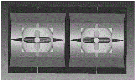
The present invention proposes a lens for a head-mounted display device, which includes biconvex lenses and plano-concave cylindrical mirrors arranged side by side; the biconvex lenses are arranged on the side near the human eye, and the plano-concave cylindrical mirror is arranged on the side of the far human eye; The biconvex lens includes aspheric surface I and aspheric surface II, and the plano-concave cylindrical lens includes aspheric surface III and aspheric surface IV; the aspheric surface I is close to the human eye, aspheric surface II and aspheric surface III are opposite, and aspheric surface IV is a plane . With the head-mounted display device designed by the present invention, the original display image does not need any preprocessing, and the image is compressed in the Y direction by the optical lens, and the size in the X direction remains unchanged. As a result, the aspect ratio of the image is compressed from 8:9 to 4:3, which is presented on the human retina. And the lens lens is easy to mold, the MTF and SPOT and LCA aberrations are well corrected, and its manufacturing cost and weight are greatly reduced.

Description

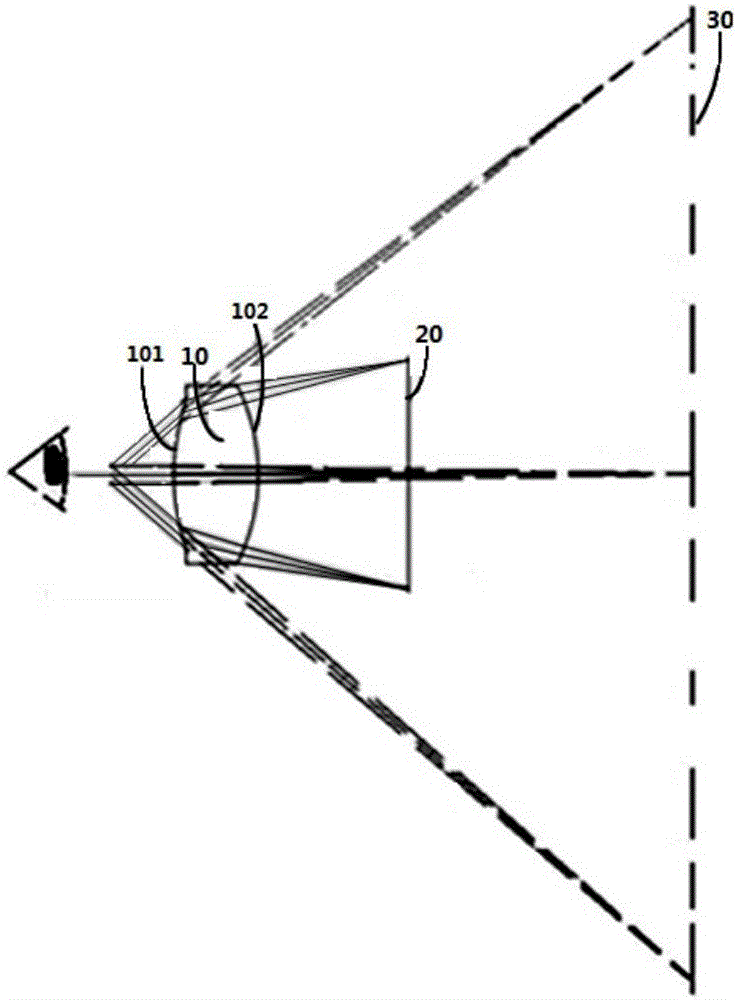
technical field [0001] The invention relates to a lens for a head-mounted display device and the head-mounted device, which are applied in the field of consumer electronics. Background technique [0002] With the advancement of the display component manufacturing industry and the emergence of 3D technology, there has been a boom in wearables in the field of consumer electronics, and head-mounted displays, as an early technology, have once again entered people's sight. As a technology that has been applied in the civilian field in recent years, head-mounted displays are developing in the direction of miniaturization, high performance, and low cost. A general head-mounted display will enlarge the image on the micro-display and finally present it on the player's retina, bringing the current two-dimensional plane picture to the player with a more three-dimensional and more impactful sense, creating an immersive sense of reality . [0003] At present, some well-known companies ...

Claims


Application Information

Patent Timeline
Patent Type & Authority Patents(China)
IPC IPC(8): G02B27/01G02B27/00
Inventor 杨春
Owner GOERTEK OPTICAL TECH CO LTD
Why Eureka
Eureka Blog
Learn More