Computer rotating shaft positioning mechanism

A positioning mechanism and computer technology, applied in the direction of electrical digital data processing, instruments, digital data processing parts, etc., can solve the problem of single-direction rotation of notebook computers

Active Publication Date: 2014-09-17
安捷资讯科技(苏州)有限公司
View PDF6 Cites 1 Cited by
  • Summary
  • Abstract
  • Description
  • Claims
  • Application Information

AI Technical Summary

Problems solved by technology

However, if the notebook computer is used as a tablet computer at the same time, the LCD panel of the notebook computer will be rotated 180 degrees (to achieve that the LCD panel and the computer motherboard are on the same plane), and even the computer motherboard will be turned to a back-to-back state with the LCD panel, so that Laptops are used as tablet display screens, and traditional notebooks are not competent. The reason is that the rotation of existing notebooks can only be rotated in one direction, and can only be rotated within less than 180 degrees (usually 165 degrees)

Method used


Image

  • Computer rotating shaft positioning mechanism
  • Computer rotating shaft positioning mechanism
  • Computer rotating shaft positioning mechanism

Examples


Embodiment Construction

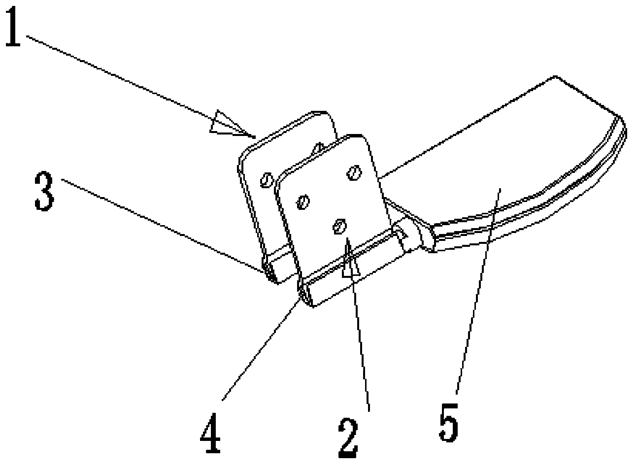
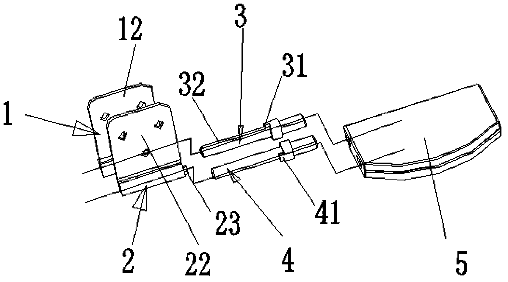
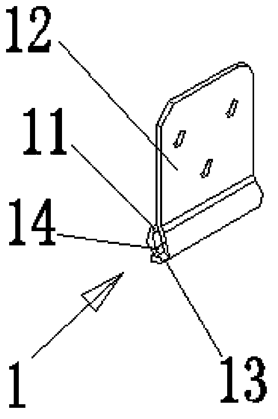
[0028] combine figure 1 , figure 2 , image 3 , Figure 4 and Figure 5 , as described in detail below:

[0029] A computer rotating shaft positioning mechanism, which is installed between the main board of the computer and the LCD panel, including a first roll 1 connected to and fixed on the LCD screen, a second roll 2 connected to and fixed on the main board of the computer, and one end extending into and tightly fitted The first mandrel 3 in the rolling hole of the first rolling circle 1, one end is inserted into and tightly fitted into the second mandrel 4 in the rolling hole of the second rolling circle 2, the first mandrel 3 The other end of the other end and the other end of the second mandrel 4 are fixed side by side on a computer base 5, and the first rolling circle 1 and the second rolling circle 2 are fixed on the computer base 5 side by side. The first rolling circle 1 For being bent into a rolling cylinder with a first axial opening groove 11 along one end b...


PUM


Abstract

The invention provides a computer rotating shaft positioning mechanism, which is arranged between a computer mainboard and a liquid crystal screen board and comprises a first circle rolling part, a second circle rolling part, a first mandrel and a second mandrel, wherein the first circle rolling part is fixedly connected with the liquid crystal screen board, the second circle rolling part is fixedly connected with the computer mainboard, one end of the first mandrel extends into a circle rolling hole of the first circle rolling part and is tightly matched with the circle rolling hole of the first circle rolling part, one end of the second mandrel extends into a circle rolling hole of the second circle rolling part and is tightly matched with the circle rolling hole of the second circle rolling part, the other end of the first mandrel and the other end of the second mandrel are simultaneously, parallelly and fixedly arranged on a computer base, the first circle rolling part is a circle rolling tube which is formed by bending a rigid board along one end and is provided with a first axial opening groove, the first circle rolling part extends into a first end edge used for fixedly connecting the liquid crystal screen board along the other end, the second circle rolling part is a circle rolling tube which is formed by bending a rigid board along one end and is provided with a second opening groove, and the second circle rolling part extends into a second end edge used for connecting the computer mainboard along the other end. The computer rotating shaft positioning mechanism has the advantages that the liquid crystal screen board can singly rotate, in addition, the computer mainboard can also rotate relative to the opposite direction of the liquid crystal display board, and the use requirements of a traditional notebook computer and a tablet personnel computer are met.

Description

technical field [0001] The invention belongs to the improvement of a computer positioning shaft, in particular to a positioning shaft mechanism used for conversion between a notebook computer and a tablet computer. Background technique [0002] At present, the opening angle of notebooks in the computer industry is usually 135 degrees to 165 degrees, and the largest can only be opened to 180 degrees, which has met the usual requirements of users. However, if the notebook computer is used as a tablet computer at the same time, the LCD panel of the notebook computer will be rotated 180 degrees (to achieve that the LCD panel and the computer motherboard are on the same plane), and even the computer motherboard will be turned to a back-to-back state with the LCD panel, so that Notebook computer is used as tablet computer display screen, and traditional notebook computer is not competent, traces it to its cause: the rotation of existing notebook computer can only rotate in one dir...

Claims


Application Information

Patent Timeline
Patent Type & Authority Applications(China)
IPC IPC(8): G06F1/16
Inventor 赵全利
Owner 安捷资讯科技(苏州)有限公司
Why Eureka
Try Eureka