A Novel Device Release Device for Implantation

A release device and device technology, applied in the field of medical devices, can solve the problems of not having an ideal implant device release device, affecting the quality of life of patients after recovery, serious tissue compression, etc., so as to make up for insufficient autologous penetration force and be beneficial to Accurate positioning, the effect of reducing sheath diameter

Active Publication Date: 2016-08-24
NINGBO JENSCARE BIOTECHNOLOGY CO LTD
View PDF6 Cites 2 Cited by
  • Summary
  • Abstract
  • Description
  • Claims
  • Application Information

AI Technical Summary

Problems solved by technology

The advantage of this design is that it can make full use of the length of the bracket, and then release the bracket after it is released to the required size; but its problem is that when the bracket is released to the required size, the support force of the bracket will cause one end of the bracket to be pulled from the bracket. The memory effect of the shape memory alloy alone cannot ensure safety.
[0007] In the existing technology, the design of the stent mostly pursues a high supporting force in order to achieve a firm anchoring, which seriously compresses the tissues near the anchoring area, leading to various complications, such as the installation of a permanent pacemaker due to the compression of the conduction bundle, which affects the QOL
At the same time, for areas that are difficult to anchor in human anatomy, such as the annulus of the mitral valve, the existing stent design has not found a good anchoring solution, and even if the support force of the stent is increased, the stent may not be able to be firmly fixed.
There are various indications that although the techniques described above have certain effects in interventional therapy, there is no ideal release device for implanted instruments that can achieve firm anchoring, controllable release, and re-sheathing

Method used


Image

  • A Novel Device Release Device for Implantation
  • A Novel Device Release Device for Implantation
  • A Novel Device Release Device for Implantation

Examples


specific Embodiment 1

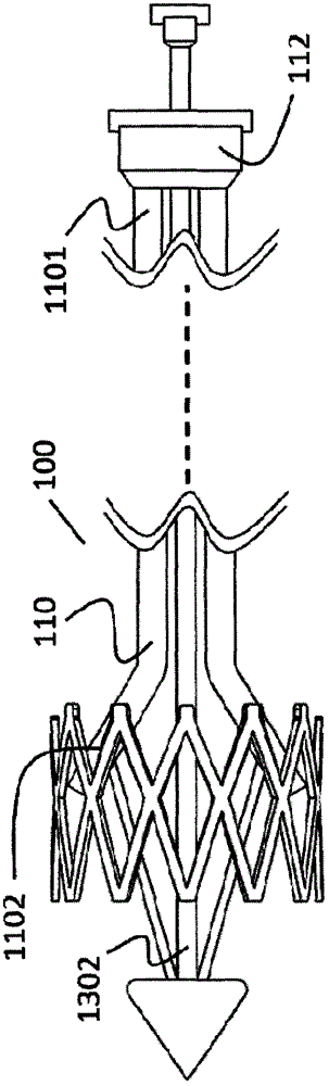
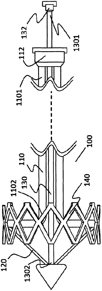
[0054] Such as Figure 1a and Figure 1b As shown, a novel implant device release device 100, the release device 100 includes a spreader rod 110, a spreader rod operating member 112, a control rod 120, a moving rod 130 and a moving rod operating member 132. The opening rod 110 is a hollow tube, the distal part 1102 of the spreading rod 110 can be bent as a whole or partially, and the proximal end 1101 of the spreading rod 110 is fixedly connected with the spreading rod operating part 112, so One end of the control rod 120 is connected to the distal part 1102 of the expansion rod 110, the other end of the control rod 120 is connected to the distal part 1302 of the moving rod 130, and the proximal end of the moving rod 130 1301 is fixedly connected with the moving rod operating member 132 , and moves the moving rod operating member 132 relative to the spreading rod operating member 112 to realize closing and opening of the spreading rod 110 . The spreading rod operating part 11...

specific Embodiment 2

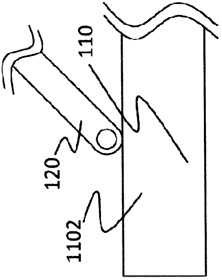
[0057] The difference from the specific example 1 is that, as another preferred implementation mode, such as Figure 5a As shown, one end of the control rod 120 is connected to the spreading rod 110 through a hinge mechanism. The hinge mechanism includes a boss 127 and a rotating shaft 122. The boss 127 is fixed on the outer wall of the spreader rod 110 by means of welding, gluing, fastening or binding, and the boss 127 is located on the The distal portion 1102 of the spreading rod 110, the boss 127 is provided with a hole 1270, one end of the control rod 120 is provided with an opening 123, and on the side wall of the opening 123 of the control rod 120 A hole 1230 is provided, the boss 127 is located on one side of the opening 123, the rotating shaft 122 passes through the hole 1270 on the boss 127 and the hole 1230 of the control rod 120, so The axis of the rotating shaft 122 is perpendicular to the axis of the spreading rod 110 . As another preferred embodiment, such as ...

specific Embodiment 3

[0060] Such as Figure 8a As shown, a novel implant device release device 200, the release device 200 includes a spreader rod 210, a spreader rod operating member, a control rod 220, a moving rod 230 and a moving rod operating member, the spreading rod 210 is a hollow tube, the distal part 2102 of the expansion rod 210 can be bent integrally or partially, the proximal end of the expansion rod 210 is fixedly connected with the expansion rod operating part, the control rod 220 One end is connected on the far-end part 2102 of described expansion rod 210, the other end of described control rod 220 is connected on the far-end part 2302 of described moving rod 230, and the proximal end of described moving rod and described moving rod The operating member is fixedly connected, moving the moving rod operating member relative to the spreading rod operating member can realize the closing and opening of the spreading rod 210, and the release device also includes an anchor needle and an a...


PUM


Abstract

The invention relates to a novel device for implanting instruments, which comprises a spreading rod, a spreading rod operating part, a control rod, a moving rod and a moving rod operating part, the spreading rod is a hollow tube, and the spreading rod The distal part of the extension rod can be bent as a whole or in part, the proximal end of the expansion rod is fixedly connected with the operation part of the expansion rod, one end of the control rod is connected to the distal part of the expansion rod, and the other end of the control rod is connected to On the distal part of the moving rod, the proximal end of the moving rod is fixedly connected with the moving rod operating member, and moving the moving rod operating member relative to the spreading rod operating member can realize the spreading The closing and opening of the rod, the release device also includes an anchor needle and an anchor needle push rod, the anchor needle and the anchor needle push rod are arranged in the expansion rod, and the anchor needle The distal end of the push rod is located proximal to the anchor pin. The invention can controlly release the implanted instrument connected thereto, which is beneficial to accurate positioning and improves the success rate of operation.

Description

Technical field: [0001] The invention belongs to the field of medical devices, and in particular relates to a novel release device for implanted devices. Background technique: [0002] At present, interventional devices on the market, especially cardiovascular interventional devices, are basically divided into two types: balloon expansion and self-expanding expansion. The balloon-expandable interventional stent is generally pressed and held on the expansion balloon by the loader outside the patient's body, and then reaches the target position through the lumen in the patient's body, and the expansion balloon is filled to the original size by filling with fluid, thereby allowing the stent to expand. Most coronary stents are released in the manner described above. For target sites with larger diameters, such as the aorta, pulmonary artery, and annulus, although balloon-expandable interventional stents occupy a part of the market, such as the Endwards Sapien series, there are ...

Claims


Application Information

Patent Timeline
Patent Type & Authority Patents(China)
IPC IPC(8): A61F2/24A61F2/07A61F2/966
Inventor 李毅斌吕世文徐志云李佳楠郑德源陈志
Owner NINGBO JENSCARE BIOTECHNOLOGY CO LTD
Why Eureka
Try Eureka