Engine high-speed working condition detonation pressure reducing device

A technology for engines and working conditions, which is applied in the direction of combustion engines, engine components, machines/engines, etc., and can solve the problem of not taking into account the low-speed working conditions and high-speed working conditions of the engine, the poor sealing of the exhaust pipe system, and the structure of the supercharging system Complexity and other problems, to achieve the effect of simple structure, lower explosion pressure and reasonable design

Inactive Publication Date: 2014-09-24
SHANGHAI JIAO TONG UNIV
View PDF9 Cites 1 Cited by
  • Summary
  • Abstract
  • Description
  • Claims
  • Application Information

AI Technical Summary

Problems solved by technology

However, the existing turbocharging systems cannot take into account the low-speed operating conditions and high-speed operating conditions of the engine well.
[0003] After searching the existing technical literature, it was found that Chinese patent number ZL200410050996.3, patent name: a variable modular pulse conversion supercharging device for a turbocharged diesel engine, the patented technology provides an exhaust device in the exhaust pipe The device with continuously variable volume can better take into account the high-speed and low-speed working conditions of the engine; but the change of the exhaust volume in the exhaust pipe is realized by moving the moving rod up and down, which requires an additional A special control mechanism is used to control the movement of the moving rod, so that the structure of the booster system becomes more complicated, and the sealing of the exhaust pipe system is also poor under high temperature conditions.

Method used


Image

  • Engine high-speed working condition detonation pressure reducing device
  • Engine high-speed working condition detonation pressure reducing device
  • Engine high-speed working condition detonation pressure reducing device

Examples


Embodiment

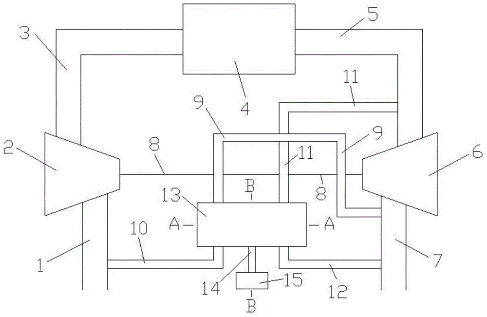
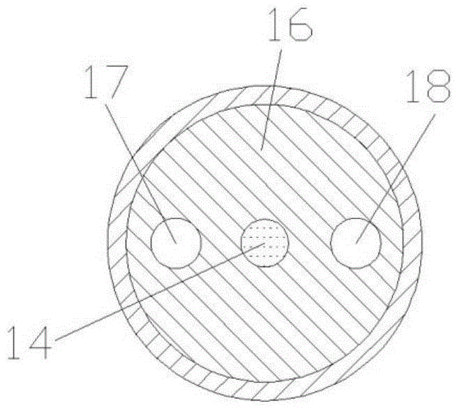
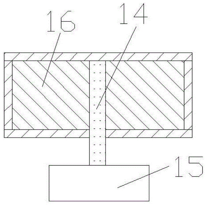
[0015] Such as Figure 1 to Figure 3 Shown, the present invention comprises compressor intake pipe 1, compressor 2, engine intake pipe 3, engine 4, engine exhaust pipe 5, turbine 6, turbine exhaust pipe 7, connecting shaft 8, first connecting pipe 9, the first Two connecting pipes 10, a third connecting pipe 11, a fourth connecting pipe 12, an adjustment mechanism 13, a rotating shaft 14, a stepping motor 15, a rotating body 16, a first through pipe 17 and a second through pipe 18, the compressor 2 The air inlet and outlet are respectively connected with the air outlet of the compressor intake pipe 1 and the air inlet of the engine air intake pipe 3, and the air inlet and outlet of the engine 4 are respectively connected with the air outlet of the engine air inlet pipe 3 and the air inlet of the engine exhaust pipe 5 , the air inlet and outlet of the turbine 6 are connected with the air outlet of the engine exhaust pipe 5 and the air inlet of the turbine exhaust pipe 7 respect...


PUM


Abstract

An engine high-speed working condition detonation pressure reducing device in the technical field of machine design comprises an air compressor, an engine, a turbine, connecting pipes, an adjusting mechanism, a rotating body, penetrating pipes, a stepping motor and a rotating shaft, wherein the inlet and the outlet of the engine are respectively connected with the air outlet of an engine air intake pipe and the air inlet of an engine air exhaust pipe; the rotating body is arranged inside the adjusting mechanism; the penetrating pipes are arranged on the rotating body; one end of the rotating shaft is connected with the stepping motor; the other end of the rotating shaft penetrates through the lower wall surface of the adjusting mechanism and is fixedly connected with the rotating body together. In the engine high-speed working condition, the stepping motor drives the rotating body to rotate so as to ensure that a third connecting pipe and a fourth connecting pipe are communicated and a first connecting pipe and a second connecting pipe are communicated, and the detonation pressure of the engine is enabled to be relatively low. The device is reasonable in design, simple in structure, and suitable for air intake and exhaust system design of a supercharged engine.

Description

technical field [0001] The invention relates to an engine intake and exhaust system in the technical field of mechanical design, in particular to an engine explosion pressure reduction device under high-speed conditions. Background technique [0002] With the development of modern society, people have higher and higher requirements on the power and economy of the engine. In the case of a certain displacement, the most effective way to increase the output power of the engine is to provide more fuel for combustion. It is easy to provide more fuel to the cylinder through the injector, but it is not so easy to provide the amount of air to match the increased amount of fuel at the same time; The effect is poor. When the fuel injection volume is constant and the cylinder air intake volume is large, the combustion is better, and the fuel consumption and emissions are lower. The traditional naturally aspirated engine completely relies on the vacuum formed in the cylinder to inhal...

Claims


Application Information

Patent Timeline
Patent Type & Authority Applications(China)
IPC IPC(8): F02B37/18F02M25/07F02M26/06
CPCY02T10/12
Inventor 董广明陈进
Owner SHANGHAI JIAO TONG UNIV
Why Eureka
Try Eureka