Piezoelectric transformer for outputting voltages based on stress change

A piezoelectric transformer and output voltage technology, applied in the field of piezoelectric transformers, can solve the problems of easy damage, difficult polarization, high process requirements such as the combination of layers and layers, achieve high power output, and simplify the manufacturing process.

Active Publication Date: 2014-09-24
SUZHOU INST OF BIOMEDICAL ENG & TECH CHINESE ACADEMY OF SCI
View PDF5 Cites 6 Cited by
  • Summary
  • Abstract
  • Description
  • Claims
  • Application Information

AI Technical Summary

Problems solved by technology

Defects of the existing technology: the piezoelectric transformer that realizes voltage transformation through different polarization directions of the input and output parts, the polarization is relatively difficult, the process is relatively complicated, and the finished PT (piez

Method used


Image

  • Piezoelectric transformer for outputting voltages based on stress change
  • Piezoelectric transformer for outputting voltages based on stress change
  • Piezoelectric transformer for outputting voltages based on stress change

Examples


Example Embodiment

[0040] Embodiment 1

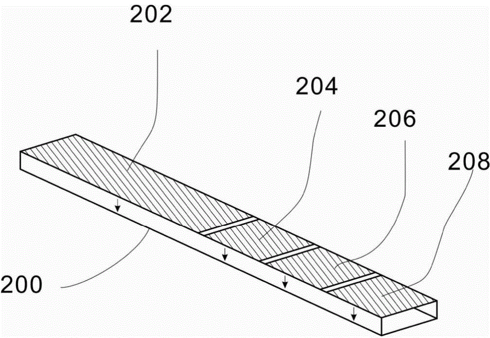
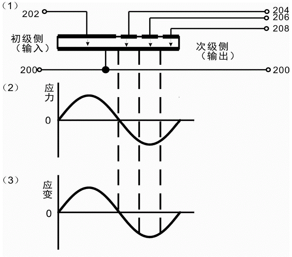
[0041] figure 1 The isometric view of the piezoelectric transformer of the full-wavelength vibration model in Embodiment 1 of the present invention, figure 2 (1) Yes figure 1 Side view of the piezoelectric transformer shown. in figure 1 with figure 2 In (1), two main surfaces perpendicular to the thickness direction of the rectangular piezoelectric plate are plated with electrodes. Of these two main surfaces, the electrode 202 on one main surface and the other main surface electrode 200 form the primary side (input end) electrode, and the main surface electrodes 204, 206, 208 and the electrode 200 can form the secondary side (output end) respectively. ) Three sub-electrodes of the electrode. The interval between the electrodes 202 and 204 (that is, the boundary point between the primary measuring electrode and the secondary side electrode) is selected at the center of the rectangular plate where the stress direction changes positively and negatively (that...

Example Embodiment

[0045] Embodiment 2

[0046] Figure 5 It is an axonometric view of the piezoelectric transformer of the full-wavelength vibration model in Embodiment 2 of the present invention, Image 6 (1) Yes Figure 5 Side view of the piezoelectric transformer shown. in Figure 5 with Image 6 In (1), a primary side (input side) electrode composed of multiple electrodes and a secondary side (output side) electrode composed of multiple electrodes are formed along the length direction and thickness direction of the rectangular plate of the piezoelectric transformer. This is a laminated structure in which a piezoelectric body layer made of piezoelectric materials such as piezoelectric ceramics and an internal electrode layer made of metal materials are stacked on each other in the thickness direction of a rectangular plate.

[0047] Image 6 In (1), there are five piezoelectric body layers and four electrode layers between the electrodes formed opposite to the two main surfaces perpendicular to t...

Example Embodiment

[0051] Embodiment 3

[0052] Figure 7 The isometric view of the piezoelectric transformer of the full-wavelength vibration model in the third embodiment of the present invention, Figure 8 (1) Yes Figure 7 Side view of the piezoelectric transformer shown. in Figure 7 with Figure 8 In (1), a secondary side (output side) electrode composed of a plurality of electrodes is formed along the length direction and the thickness direction of the rectangular plate of the piezoelectric transformer. This is a laminated structure in which a piezoelectric body layer made of piezoelectric materials such as piezoelectric ceramics and an internal electrode layer made of metal materials are stacked on each other in the thickness direction of a rectangular plate.

[0053] Figure 8 In (1), there are five piezoelectric body layers and four electrode layers between the primary side electrodes formed on two main surfaces perpendicular to the thickness direction of the rectangular plate. Electrodes ...


PUM


Abstract

The invention discloses a piezoelectric transformer for outputting voltages based on stress change and belongs to the technical field of the piezoelectric devices. A piezoelectric plate of the piezoelectric transformer comprises a primary side electrode and a secondary side electrode obtained by virtue of division according to stress distribution; each of the primary side and secondary side electrodes is composed of a plurality of sub-electrodes obtained by virtue of division according to the stress distribution of the piezoelectric transformer in different vibration models; as a result, multi-stage voltage output and high-power output of the piezoelectric transformer are realized; the electrodes are divided flexibly so that the manufacturing process can be simplified.

Description

technical field [0001] The invention discloses a piezoelectric transformer that changes output voltage based on stress, and belongs to the technical field of piezoelectric devices. Background technique [0002] In essence, a piezoelectric transformer is a power electronic device formed by organically combining two piezoelectric vibrators. One vibrator is used as the input part, and the other vibrator is used as the output part. The input part is applied with an alternating electric field. Under the action of the piezoelectric effect, the vibration is generated through the inverse piezoelectric effect, and the electrical energy is converted into mechanical energy. The output part feels this vibration, and the mechanical energy is converted into electrical energy output through the positive piezoelectric effect. From an electrical point of view, since the impedance of the input part and the output part are different in the process of energy conversion and transfer, the voltage...

Claims


Application Information

Patent Timeline
IPC IPC(8): H01L41/047H01L41/107
Inventor 邵维维李培洋崔崤峣吕铁军顾天明徐杰
Owner SUZHOU INST OF BIOMEDICAL ENG & TECH CHINESE ACADEMY OF SCI
Why Eureka
Try Eureka