A charging system for electronic products
A charging system and electronic product technology, applied in battery circuit devices, current collectors, electric vehicles, etc., can solve problems such as long charging time and abnormality, and achieve the effect of improving charging efficiency
- Summary
- Abstract
- Description
- Claims
- Application Information
AI Technical Summary
Problems solved by technology
Method used
Image

Examples
Embodiment 1
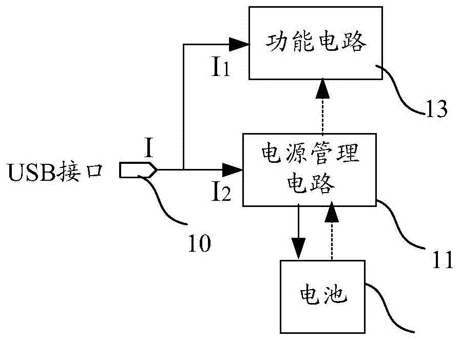
[0032] Please refer to figure 2 , the present embodiment provides a charging system for an electronic product, which is used to charge the built-in power supply of the electronic product. The built-in power supply is generally a rechargeable lithium battery 12, and the charging system includes a USB interface 101 and a power supply connected to the USB interface 101 The management circuit 11, the power management circuit 11 can obtain external power through the USB interface 101 to charge the battery 12, and the USB interface 101 of the charging system is also connected to the functional circuit 13 of the electronic product (the functional circuit 13 is Refers to the general term of power consumption circuits in electronic products, which realize the functions of electronic products by consuming the built-in power supply, such as including control chip MCU, touch circuit, display circuit, audio circuit, alarm circuit, wireless communication circuit, etc.), so The charging sys...
Embodiment 2
[0043] In fact, since the charging system in Embodiment 1 is mainly suitable for charging electronic products through the USB interface of the USB cable connected to the electronic product (for example, a notebook computer charges a mobile phone through a USB cable), the charging current of 500mA in this charging mode exists Some hidden dangers, so many existing electronic products are equipped with a power adapter seat charging function, wherein in the prior art, the charging interface of the seat charger has both a USB interface and a DC pin interface, or a charging interface can receive USB The data line transmits power (that is, charges according to the USB charging specification, such as charging a mobile phone through a laptop) and receives DC adapter charging (the DC pin interface is integrated with the USB interface). In order to describe this solution more clearly, this article As long as the electronic device can perform DC charging (charging in the form of fast charg...
Embodiment 3
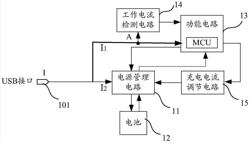
[0064] Please refer to Figure 13 The difference between the charging system of this embodiment and Embodiment 1 and Embodiment 2 is that the functional circuit of this embodiment does not have its own MCU or trigger, so the output terminal of the working current detection circuit 14 is directly connected to the charging current regulation circuit 15 , to control the charging current regulation circuit to adjust the charging current. It can also intelligently adjust the charging current when the user is charging and using it, so that the electronic product can charge the battery with a small current when the electronic product is in a high current working state. It can be quickly charged with a large current to fully improve the charging efficiency.
[0065] The charging system of this embodiment can also refer to the second embodiment to expand its functions, so as to be compatible with DC charging and DC charging. The specific circuit of each part can refer to the specific ...
PUM
 Abstract
Description
Claims
Application Information
 - R&D
- Intellectual Property
- Life Sciences
- Materials
- Tech Scout
- Unparalleled Data Quality
- Higher Quality Content
- 60% Fewer Hallucinations
Browse by: Latest US Patents, China's latest patents, Technical Efficacy Thesaurus, Application Domain, Technology Topic, Popular Technical Reports.
© 2025 PatSnap. All rights reserved.Legal|Privacy policy|Modern Slavery Act Transparency Statement|Sitemap|About US| Contact US: help@patsnap.com