Permanent magnetic speed regulation, brake or load apparatus capable of stepless adjustment of magnetic field intensity

A technology of magnetic field strength and stepless adjustment, applied in the direction of permanent magnet clutch/brake, asynchronous induction clutch/brake, etc. Process difficulties, etc.

Inactive Publication Date: 2014-09-24
林英楠
View PDF10 Cites 63 Cited by
  • Summary
  • Abstract
  • Description
  • Claims
  • Application Information

AI Technical Summary

Problems solved by technology

[0004] 1. Large installation size, high requirements for on-site installation conditions of technical transformation projects, and poor adaptability
[0005] 2. The existing known permanent magnet speed governors, permanent magnet brakes and permanent magnet loaders are due to directly adjusting the coupling distance and/or The coupling area is realized, where the relative position between the passive disk and the driving disk is dynamically changed online in real time, so at least one of the passive disk and the driving disk and its transmission shaft are axially sliding and transmitting the torque structure, This structure brings great difficulties to the product manufacturing and assembly process, and has relatively strict requirements on the technical indicators such as the material and manufacturing precision of key components, the manufacturing process is comp

Method used


Image

  • Permanent magnetic speed regulation, brake or load apparatus capable of stepless adjustment of magnetic field intensity
  • Permanent magnetic speed regulation, brake or load apparatus capable of stepless adjustment of magnetic field intensity
  • Permanent magnetic speed regulation, brake or load apparatus capable of stepless adjustment of magnetic field intensity

Examples


Embodiment 1

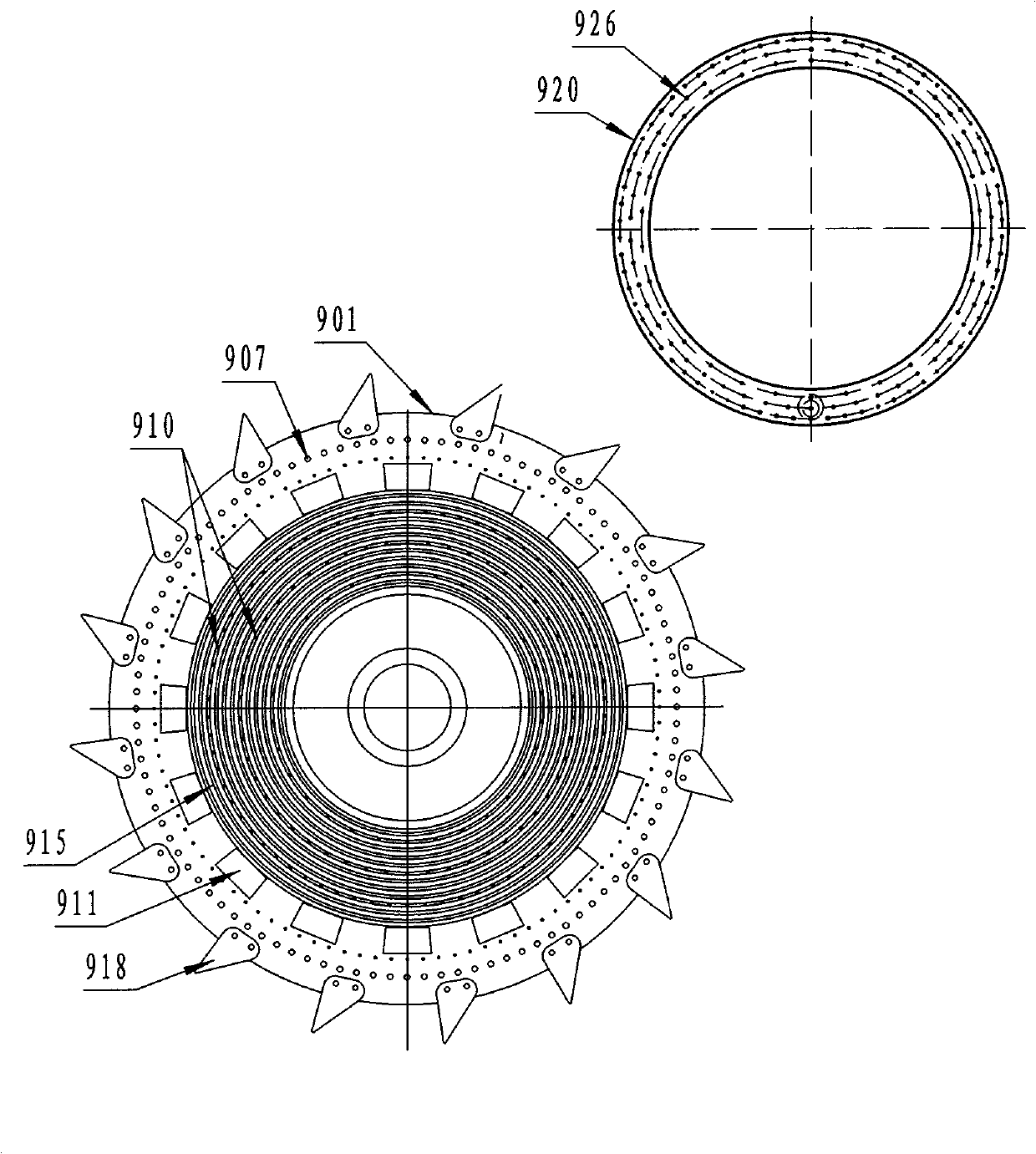
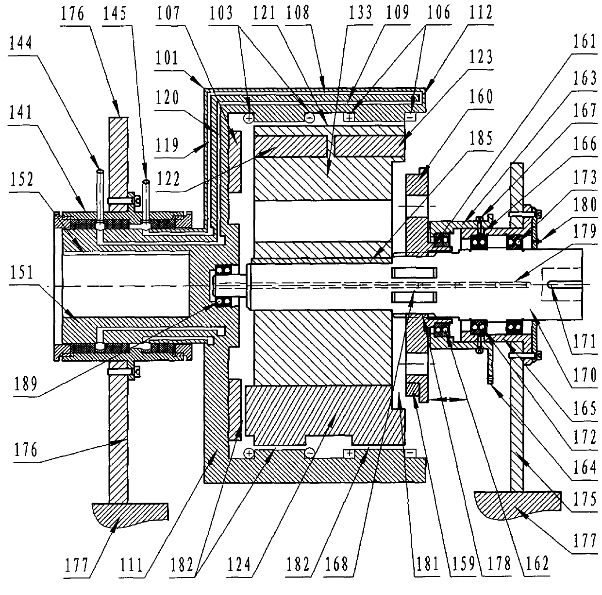
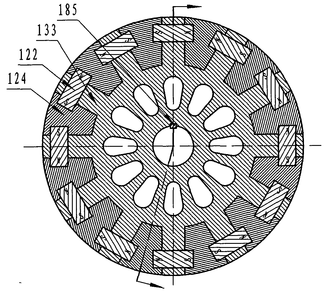
[0070] Such as figure 1 , 2 As shown in and 3, it is a turntable and drum combined permanent magnetic coupling coupling composed of "1 set of axial magnetic field + 2 sets of radial magnetic field" single-layer permanent magnetic coupling components on both sides, mainly composed of active rotor (101), passive Rotor (121), three working magnetic coupling air gaps (182), magnetic leakage magnetic circuit / air gap (181), magnetic leakage magnetic circuit air gap adjustment discs (160, 159) and transmission adjustment mechanism (170, 168, 178 , 161, 162, 163, 167, 165, 166, 172, 173, 164) form. The specific settings include: a set of axial magnetic field permanent magnetic coupling components (the axial magnetic field annular metal conductor disk 107 is coupled with the yoke 124 of the permanent disks 122 and 123) and two sets of radial magnetic field permanent magnetic coupling components in series (radial magnetic field cylindrical armature winding disk 103 is coupled with the...

Embodiment 2

[0074] Such as Figure 4 , 5 , 6, it is "2 sets of radial magnetic field + 1 set of radial magnetic field" two-layer three-sided permanent magnetic coupling assembly nested turntable drum combination type permanent magnetic coupling coupling, mainly composed of active rotor (201), passive Rotor (221), three working magnetic coupling air gaps (282), magnetic leakage magnetic circuit / air gap (281), magnetic leakage magnetic circuit air gap adjustment discs (260, 259) and transmission adjustment mechanism (270, 255, 256 , 257, 258, 254, 261, 262, 263, 264, 265, 266, 297, 298). The specific setting includes: a group of axial magnetic field permanent magnetic coupling components (the axial magnetic field annular metal conductor disc 207 is coupled with the yoke 224 of the permanent disk 223) and two groups of radial magnetic field permanent magnetic coupling components (radial The magnetic field cylindrical metal conductor disk 203 is coupled with the yoke 224 of the permanent ma...

Embodiment 3

[0077] Such as Figure 7As shown, it is a "3 sets of radial magnetic field + 1 set of axial magnetic field" two-layer three-sided permanent magnetic coupling assembly nested turntable and drum combined permanent magnetic coupling coupling, mainly composed of active rotor (301), passive rotor ( 321), three working magnetic coupling air gaps (382), flux leakage magnetic circuit / air gap (381), petal-shaped magnetic flux leakage magnetic circuit air gap adjustment disc (adjustment disc body 360, permanent magnet group 359) and transmission adjustment mechanism (370, 355, 357, 356, 358, 354, 361, 362, 363). There are two aspects different from Embodiment 2, one is that the permanent magnets (322, 323) are combined, and the two permanent magnets are spliced ​​or bonded together with N-S or S-N, that is, a group of axial magnetic field permanent magnetic coupling Components (the axial magnetic field circular metal conductor disk 307 is coupled with the yoke 324 of the permanent magn...


PUM


Abstract

The invention discloses a permanent magnetic speed regulation, brake or load apparatus capable of stepless adjustment of magnetic field intensity. The apparatus is characterized in that the apparatus is a of single-rotating disk/multi-rotating disk type structure , a single-rotating cylinder/multi-rotating cylinder type structure, a rotating disk and rotating cylinder combination type structure or a rotating disk and rotating cylinder compound structure, and is mainly composed of a driving rotor, a driven rotor, a work magnetic coupling air gap/medium, a magnetic leakage magnetic circuit/air gap, a magnetic leakage magnetic circuit air gap adjusting disc and an adjusting mechanism. The apparatus provided by the invention is applied to such technical fields as coupling transmission, load speed regulation, automatic transmission, brake and braking, load rotation, power cut-off/combination, motor energy conservation, a household electrical appliance (including an air conditioner, an electric fan and a washing machine) and the like. The technical scheme is used for designing and manufacturing a permanent magnetic speed regulator, a speed regulation shaft coupling, an automatic transmission, a braking device, a load/loading device, a centrifugation load speed regulator or a clutch or a novel energy-saving household electrical appliance.

Description

technical field [0001] The technical fields involved in the present invention include: the technical field of transmission shaft coupling drive and speed regulation, the field of automatic transmission of vehicles, the technical field of energy saving and emission reduction, the technical field of cutting / combining power, the field of isolated / sealed transmission, and the technical field of braking and braking , load / load of power equipment dynamometer, household appliances (including air conditioners, electric fans, washing machines) and other technical fields, especially a permanent magnet speed regulation, braking or load device that can steplessly adjust the magnetic field strength. Background technique [0002] Around us, permanent magnet speed regulation, braking and load devices can be applied to the coupling transmission between the output shaft of the power equipment and the load input shaft and its load speed regulation, automatic transmission, rotating brake and br...

Claims


Application Information

Patent Timeline
IPC IPC(8): H02K49/10H02K49/04
Inventor 林英楠高志宏王忠勇
Owner 林英楠
Why Eureka
Try Eureka