
An integrated device for ophthalmology

An ophthalmic and ophthalmic technology, applied in the field of ophthalmic technology, can solve the problems of high floor space requirements and hinder the application of ophthalmic devices, and achieve the effects of rapid completion, compact design and low cost

Active Publication Date: 2014-09-24
ALCON INC
View PDF5 Cites 6 Cited by
  • Summary
  • Abstract
  • Description
  • Claims
  • Application Information

AI Technical Summary

Problems solved by technology

[0003] The provision and deployment of multiple devices for ophthalmology is disadvantageous due to high floor space requirements and

Method used


Image

  • An integrated device for ophthalmology
  • An integrated device for ophthalmology
  • An integrated device for ophthalmology

Examples


Embodiment Construction

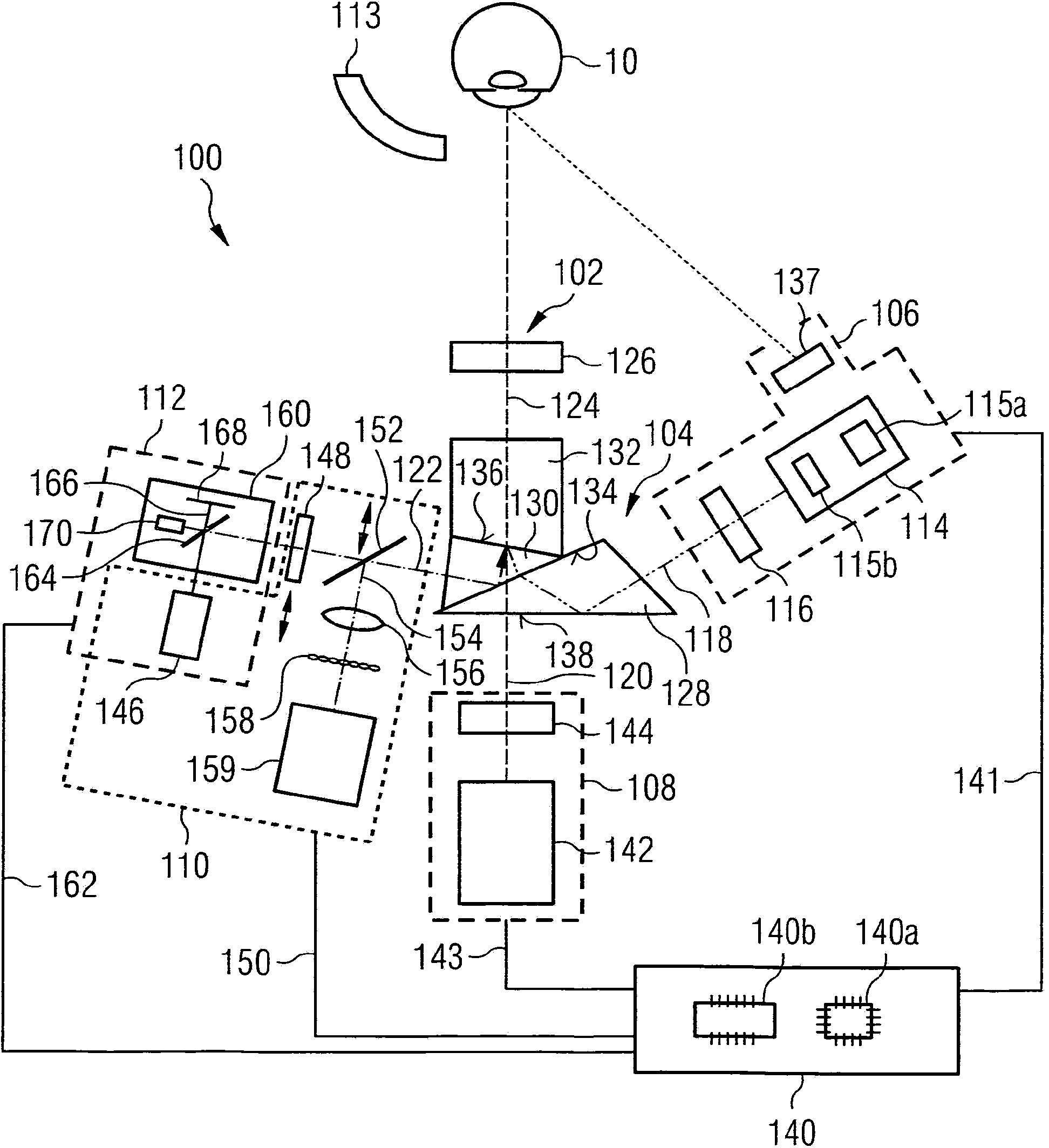
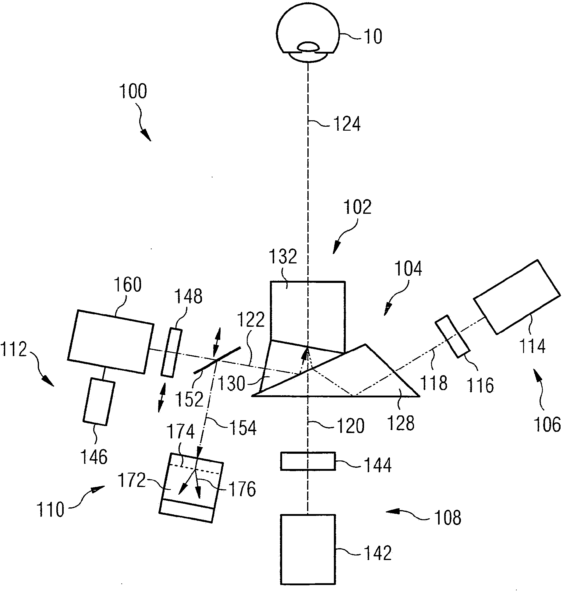
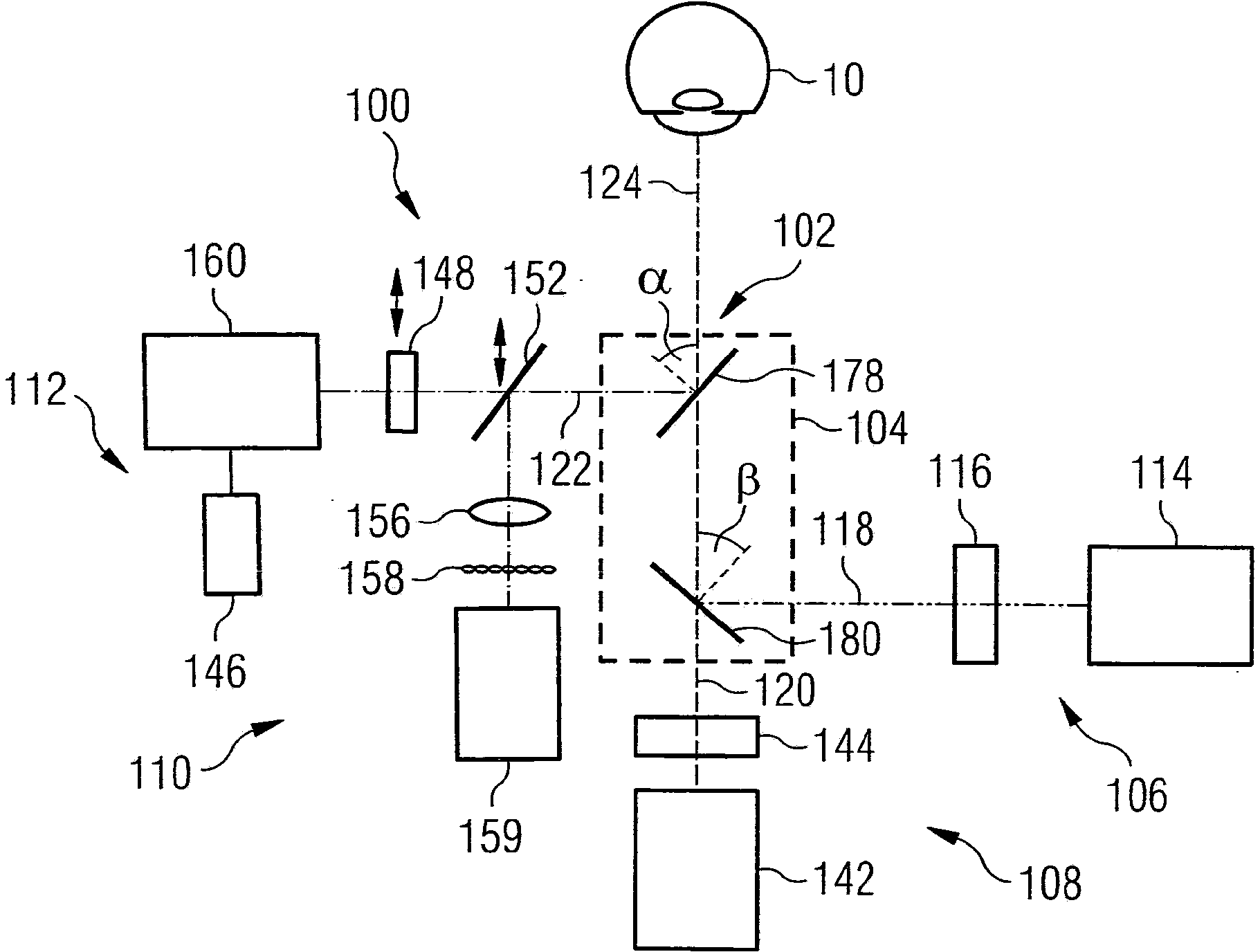
[0039] figure 1 The functional arrangement of the optical components in the device 100 for ophthalmic radiation is schematically shown. Throughout, the same reference numerals designate equivalent or alternative features of components. The apparatus 100 includes a radiation interface 102 (eg, a radiation outlet), an optical splitter coupler 104 , and a plurality of ophthalmic units 106 , 108 , 110 and 112 . The device comprises a support or contact surface 113 for the patient's head. The support or contact surface defines the position of the eye 10 relative to the device 100 or relative to the radiation interface 102 .

[0040] figure 1 The ophthalmic unit 106 in the embodiment shown in is a lighting unit comprising a projector 114 for slit lamp illumination at the eye. The projector 114 includes a light source 115a (eg, one or more light emitting diodes (LEDs)) and a microdisplay 115b. The microdisplay 115b may comprise a silicon wafer as a base material and addressing e...


PUM


Abstract

A device (100) for ophthalmic radiation is provided. The device comprises a radiation interface (102), an optical branch coupler (104), and a plurality of ophthalmic units (106, 108, 110, 112). The radiation interface is adapted to at least one of output and capture radiation on an optical path (124). The optical path is directable towards a patient's eye. The optical branch coupler is adapted to couple output radiation from a plurality of optical branches (118, 119, 120, 122, 123) into the optical path and to couple captured radiation from the optical path into the optical branches. The captured radiation is spectrally split by the optical branch coupler into the optical branches. Each of the optical branches has a different spectral range. Each of the plurality of ophthalmic units is arranged to couple to one of the optical branches.

Description

technical field [0001] The present invention generally relates to ophthalmic techniques. In particular, the invention relates to an integrated device for ophthalmology for providing and / or analyzing radiation. Background technique [0002] Devices for ophthalmic diagnostics have been designed for very specific diagnostic applications. As an example, the " Topolyzer TM Vario TM "as well as" Oculyzer TM II" provide topographic and velocimetric measurements, respectively. Furthermore, some current devices for ophthalmic diagnostics accommodate two different measurement techniques that can only be applied one after the other. According to "Visionix L80Wave+" by Luneau / Visionix It is a typical device of the latter. [0003] The provision and deployment of multiple ophthalmic devices is disadvantageous due to the high space requirement and the multiple costs for investment and maintenance, which can even hinder the use of ophthalmic devices in medical practice or in the c...

Claims


Application Information

Patent Timeline
IPC IPC(8): A61B3/10A61B3/14A61B3/00A61B5/00
CPCA61B3/107A61B3/1015A61B3/0008A61B3/113A61B3/102A61B5/0066G02B27/141A61B3/0091A61B3/145G02B27/1013A61B3/18A61B3/10A61B3/14A61B5/00A61B6/00A61F9/00A61N5/00
Inventor 克里斯托夫·德尼茨基克里斯蒂安·维尔纳
Owner ALCON INC
Learn More