High-pressure fuel supply pump equipped with electromagnetically driven inlet valve
An electromagnetically driven, high-pressure fuel technology, which is applied to fuel injection devices, fuel injection pumps, and fuel injection devices with special measures to affect the magnetic flux. Fluctuation in ejection amount, effect of eliminating unstable behavior
- Summary
- Abstract
- Description
- Claims
- Application Information
AI Technical Summary
Problems solved by technology
Method used
Image

Examples
no. 1 example 〕
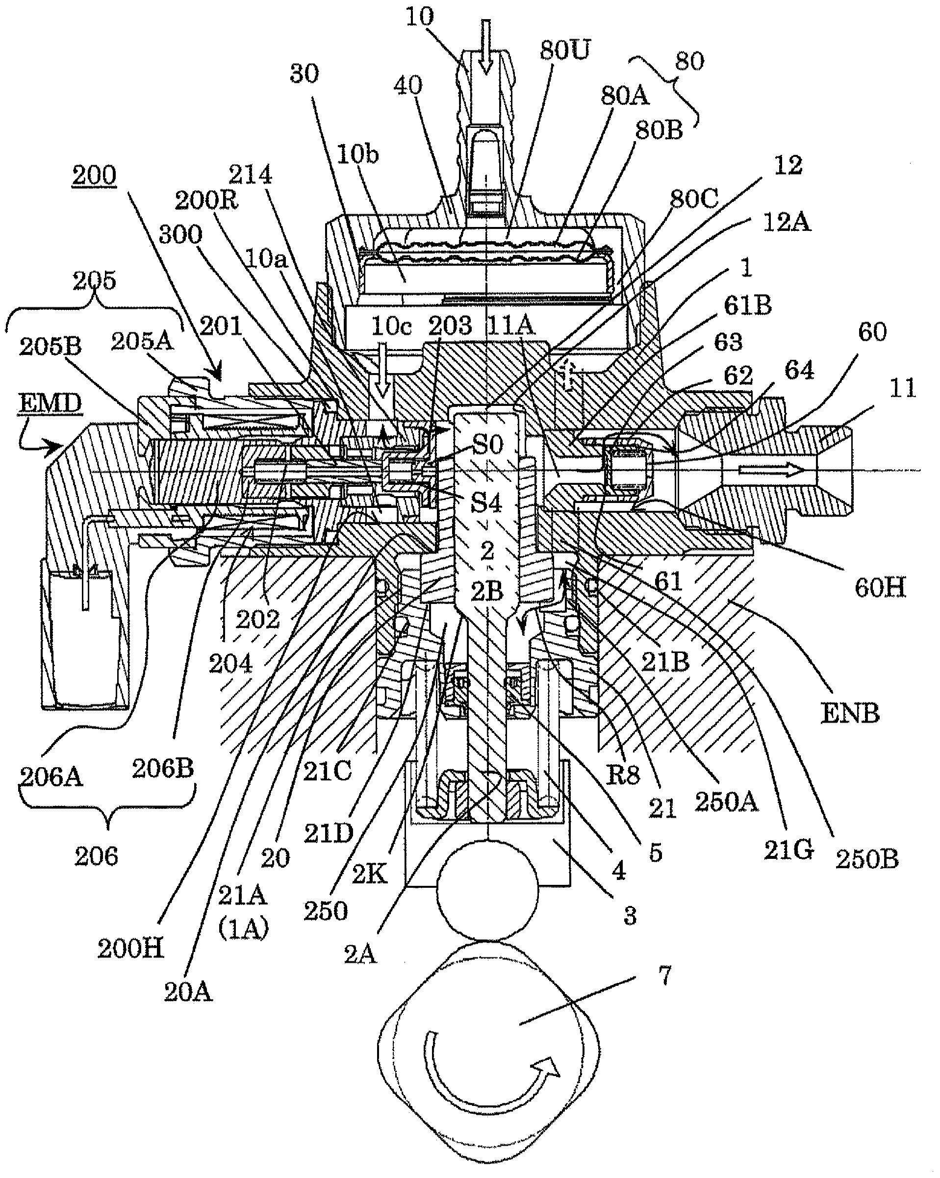
[0036] based on figure 1 Turning to FIG. 4, a first embodiment of the high-pressure fuel supply pump embodying the present invention will be described. due to figure 1 It is not possible to mark small parts in the symbol, so as far as the symbols in the description are concerned, there will be a figure 1 Parts without symbols in , are shown with symbols in the enlarged drawings described later.
[0037] The pump housing 1 is provided with a recessed portion 12A forming a bottomed cylindrical space with an open end, and the hydraulic cylinder 20 is inserted into the recessed portion 12A from the open end side. The outer periphery of the hydraulic cylinder 20 and the pump housing 1 are sealed by a crimping portion 20A. In addition, since the plunger 2 is slidingly fitted to the hydraulic cylinder 20, the inner peripheral surface of the hydraulic cylinder 20 and the outer peripheral surface of the plunger 2 are sealed by the fuel that penetrates between the sliding fitting sur...
no. 2 example
[0092] A second embodiment will be described based on FIG. 5(A) and FIG. 5(B). Parts having the same functions as those in the first embodiment are denoted by the same symbols. The electromagnetically driven suction valve of the second embodiment shown in FIG. 5(A) and FIG. 5(B) is a so-called outward opening type valve provided with a valve element 203 on the pressurization chamber 12 side of a valve seat 214S. The valve element 203 is arranged closer to the pressurization chamber side (downstream side of the valve seat) than the valve seat 214S, and a valve stopper S0 for restricting the valve opening position of the valve element 203 is provided between the pressurization chamber 12 and the valve element 203 . Through-holes SN1-SN6 (corresponding to slits Sn1-Sn3 of the first embodiment) forming fuel passages are provided on the valve stopper S0 on the outer side in the circumferential direction of the valve body 203 . One end of the cylindrical fuel introduction passage ...
no. 3 example
[0095]A third embodiment will be described based on FIG. 6(A) and FIG. 6(B). Parts having the same functions as those in the first embodiment are denoted by the same symbols. The electromagnetically driven suction valve of the third embodiment shown in FIG. 6(A) and FIG. 6(B) is a so-called outward opening type valve provided with a valve element 203 on the side of the pressurizing chamber 12 of the valve seat 214S. The valve element 203 is arranged on the pressurization chamber side (downstream side of the valve seat) from the valve seat 214S, and a valve stopper for restricting the valve opening position of the valve element 203 is provided between the pressurization chamber 12 and the valve element 203 S0. Through-holes SN1-SN6 (corresponding to the notches Sn1-Sn3 of the first embodiment, corresponding to the notches Sn1-Sn3 of the second embodiment) are provided to pass through the valve stopper S0 obliquely outward from the end surface of the valve stopper S0 on the pre...
PUM
 Abstract
Description
Claims
Application Information
 - R&D
- Intellectual Property
- Life Sciences
- Materials
- Tech Scout
- Unparalleled Data Quality
- Higher Quality Content
- 60% Fewer Hallucinations
Browse by: Latest US Patents, China's latest patents, Technical Efficacy Thesaurus, Application Domain, Technology Topic, Popular Technical Reports.
© 2025 PatSnap. All rights reserved.Legal|Privacy policy|Modern Slavery Act Transparency Statement|Sitemap|About US| Contact US: help@patsnap.com