Internal combustion engine

a combustion engine and internal combustion technology, applied in the direction of machines/engines, oscillatory slide valves, non-mechanical valves, etc., can solve the problems of engine only being run at lower revolutions, energy loss from internal volume, and reducing efficiency

Inactive Publication Date: 2009-07-14
CLEEVES ENGINES
View PDF43 Cites 74 Cited by
  • Summary
  • Abstract
  • Description
  • Claims
  • Application Information

AI Technical Summary

Benefits of technology

[0090]One advantage of the invention is that energy losses are minimized in all modes. With reference to FIGS. 1, 2, and 5, it can be seen that the internal volume 170 is entirely defined by inner surfaces of the sleeve portions 76 of the left and right valve arrangements 14 and 16, an inner surface of the inner portion 92, and facing surfaces of the left and right pistons 120 and 154. A volume of the internal volume 170 is thus approximately the area of the left piston 120 multiplied by a distance between the facing surfaces of the left piston 120 and the right piston 154. It is also within the scope of the invention that the internal volume 170 be slightly larger than the surface area of the face of the left piston 120 multiplied by the distance between the facing surfaces of the left and right pistons 120 and 154, for example 20% larger, more preferably 10% larger when the left and right pistons 120 and 154 are at their maximum stroke. Because of the facing relationship of the left and right pistons 120 and 154, there is no cylinder head for the left piston 120 through which heat can escape, nor is there a cylinder head for the right piston 154 through which heat can escape. The facing relationship between the left and right pistons 120 and 154 thus assists in containment of heat energy, with a corresponding increase in efficiency.

Problems solved by technology

Heat is transferred to the cylinder head and conducts through the cylinder head, thereby resulting in energy losses from the internal volume and a reduction in efficiency.
A large stroke results in high forces created on the piston and other components of the engine, so that the engine can only be run at lower revolutions per minute with a corresponding reduction in power.
Partial-power operation in a conventional combustion engine is also less efficient than full-power operation because a gas within the internal volume does not expand and cool down fully during partial-power operation, resulting in a relatively high temperature of the gas when it is exhausted.
The heat in the exhaust gas is an energy loss that results in a reduction in efficiency.

Method used


Image

  • Internal combustion engine
  • Internal combustion engine
  • Internal combustion engine

Examples


Embodiment Construction

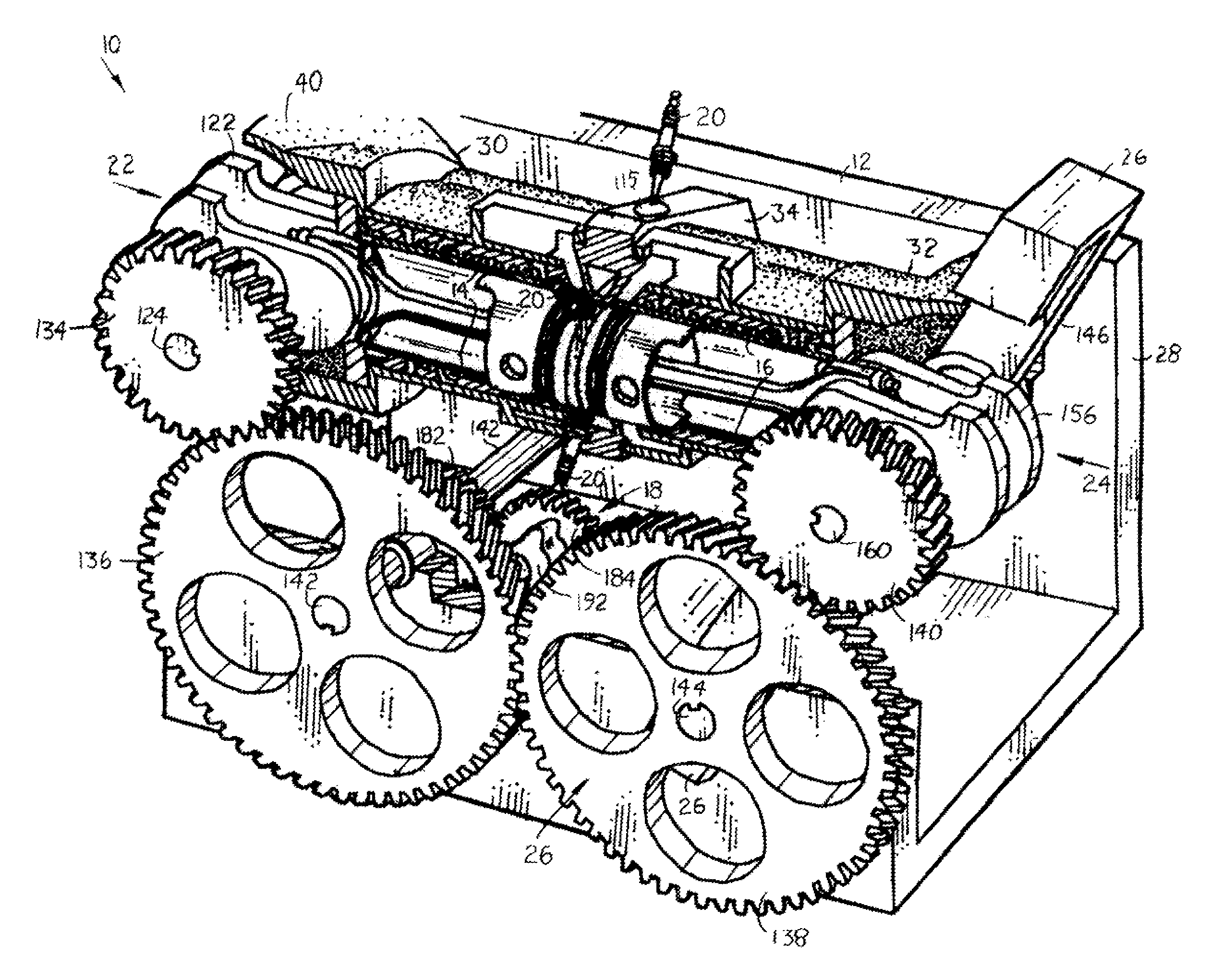
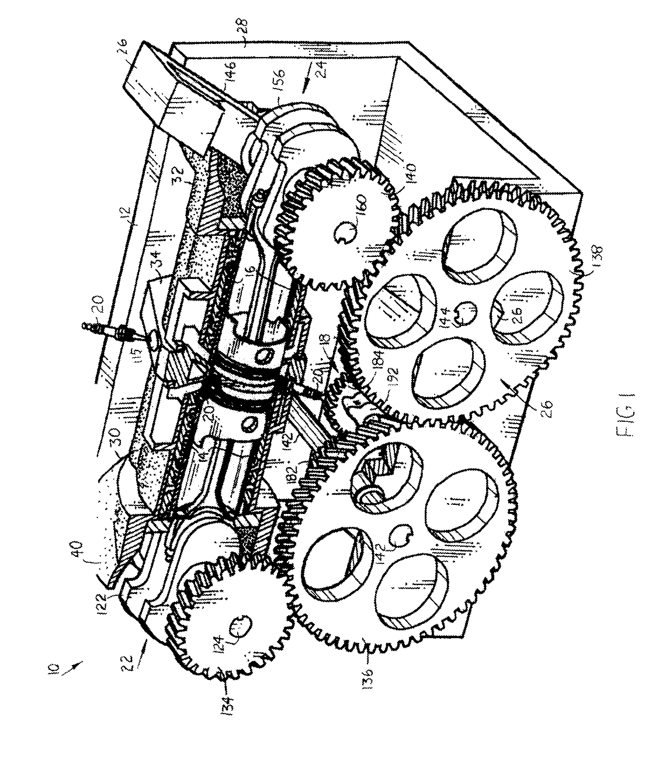
[0044]FIG. 1 of the accompanying drawings illustrates components of an internal combustion engine 10, according to an embodiment of the invention, including a body 12, left and right valve arrangements 14 and 16, components of a valve-control system 18, spark plugs 20, left and right power delivery arrangements 22 and 24, respectively, and a combustion chamber size-varying mechanism 26.

[0045]The body 12 includes a base portion 28, left and right castings 30 and 32, and a central connecting piece 34. The left and right castings 30 and 32 are mounted to the central connecting piece 34. The assembly, including the left and right castings 30 and 32 and the central connecting piece 34, is then secured to the base portion 28 to form a unitary piece with the base portion 28, the castings 30 and 32 and the central connecting piece 34 being immovably connected to one another.

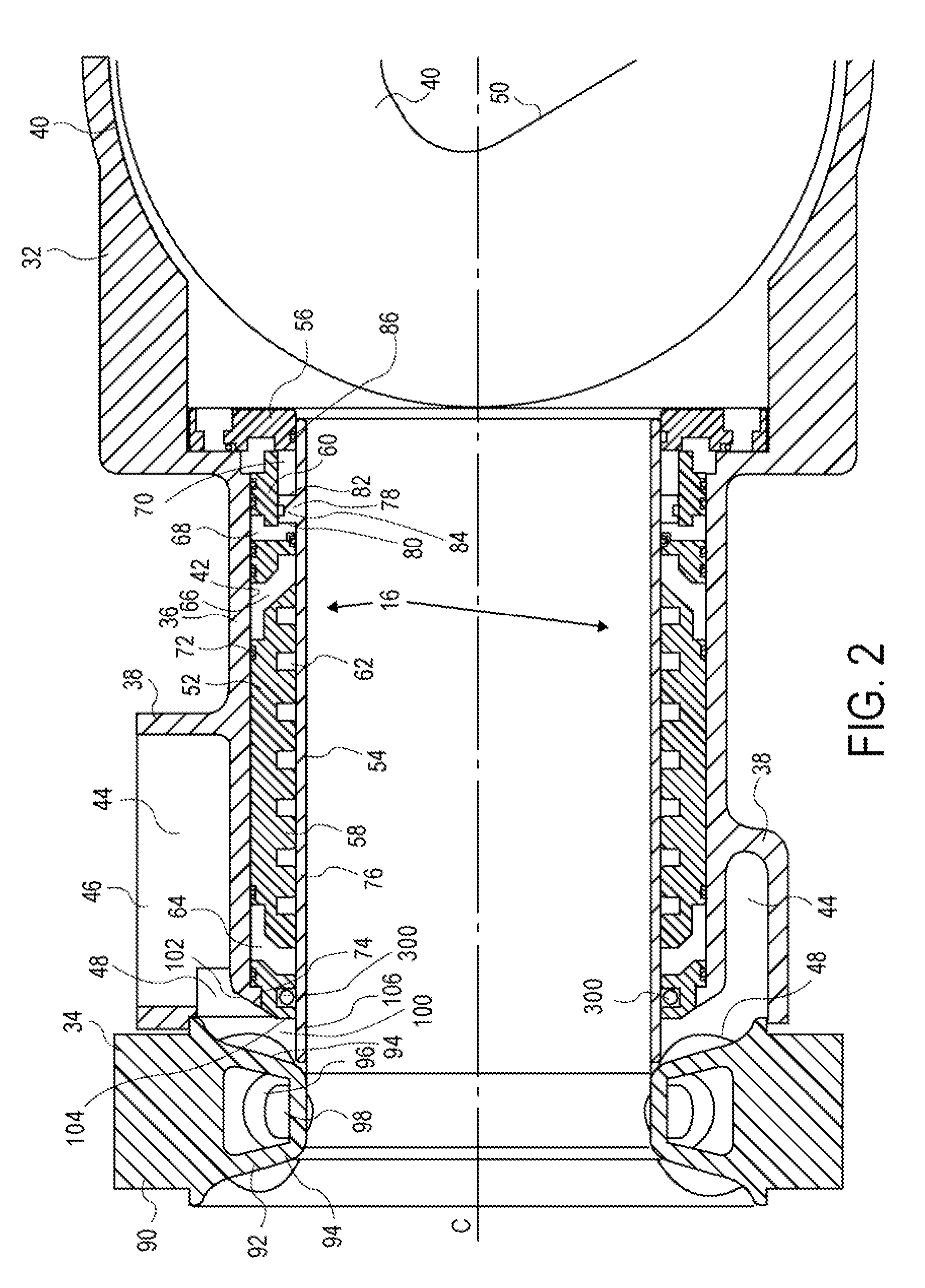
[0046]As shown in FIG. 2, the right casting 32 includes a cylinder block portion 36, an air intake and distribution po...


PUM


Abstract

An internal combustion engine is provided. Facing pistons eliminate a cylinder head, thereby reducing heat losses through a cylinder head. Facing pistons also halve the stroke that would be required for one piston to provide the same compression ratio, and the engine can thus be run at higher revolutions per minute and produce more power. An internal sleeve valve is provided for space and other considerations. A combustion chamber size-varying mechanism allows for adjustment of the minimum size of an internal volume to increase efficiency at partial-power operation. Variable intake valve operation is used to control engine power.

Description

CROSS-REFERENCE TO RELATED APPLICATIONS[0001]This application claims priority from U.S. Provisional Patent Application No. 60 / 792,995, filed on Apr. 18, 2006 and U.S. Provisional Patent Application No. 60 / 853,095 filed on Oct. 20, 2006, all of which are incorporated herein by reference in their entirety.BACKGROUND OF THE INVENTION[0002]1). Field of the Invention[0003]This invention relates to an internal combustion engine.[0004]2). Discussion of Related Art[0005]Internal combustion engines are used to power vehicles and other machinery. A typical reciprocating internal combustion engine includes a body, a piston, at least one port, at least one valve, a crankshaft (which serves as a drive shaft), and a connecting rod. The body defines a cylinder. The piston is located inside the cylinder so that a surface of the piston and a wall of the cylinder define an internal volume. The port is located in the body, and allows air and fuel into and exhaust gas out of the internal volume. The va...

Claims


Application Information

Patent Timeline
Patent Type & Authority Patents(United States)
IPC IPC(8): F02B75/04F01L1/34F01L7/00F02B75/28F01L9/10
CPCF01L5/06F02F1/14F02B25/08F02B75/282F02D13/0269F02D13/028F02D15/02F02F1/186F01L7/00F02B75/28F01L7/04F01L9/02F01L2820/033Y02T10/142F01P2003/021Y02T10/12F01L9/10F02B75/24
Inventor CLEEVES, JAMES M
Owner CLEEVES ENGINES
Why Eureka
Try Eureka