Noise suppression device
A noise suppression and noise technology, which is applied in the field of noise suppression devices, can solve the problems of voice degradation, voice recognition rate reduction, etc., and achieve the effect of less sound distortion
- Summary
- Abstract
- Description
- Claims
- Application Information
AI Technical Summary
Problems solved by technology
Method used
Image
Examples
Embodiment approach 1
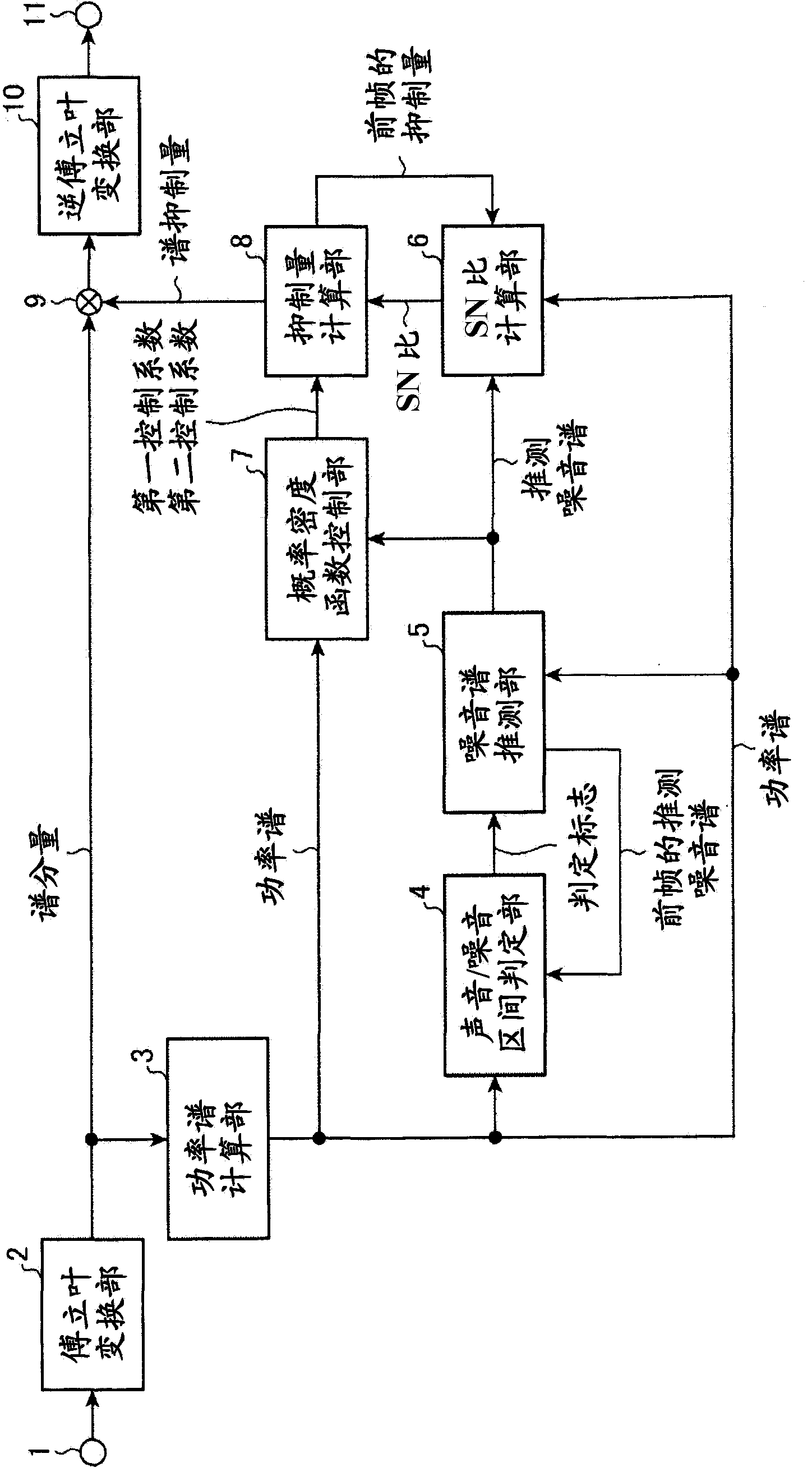
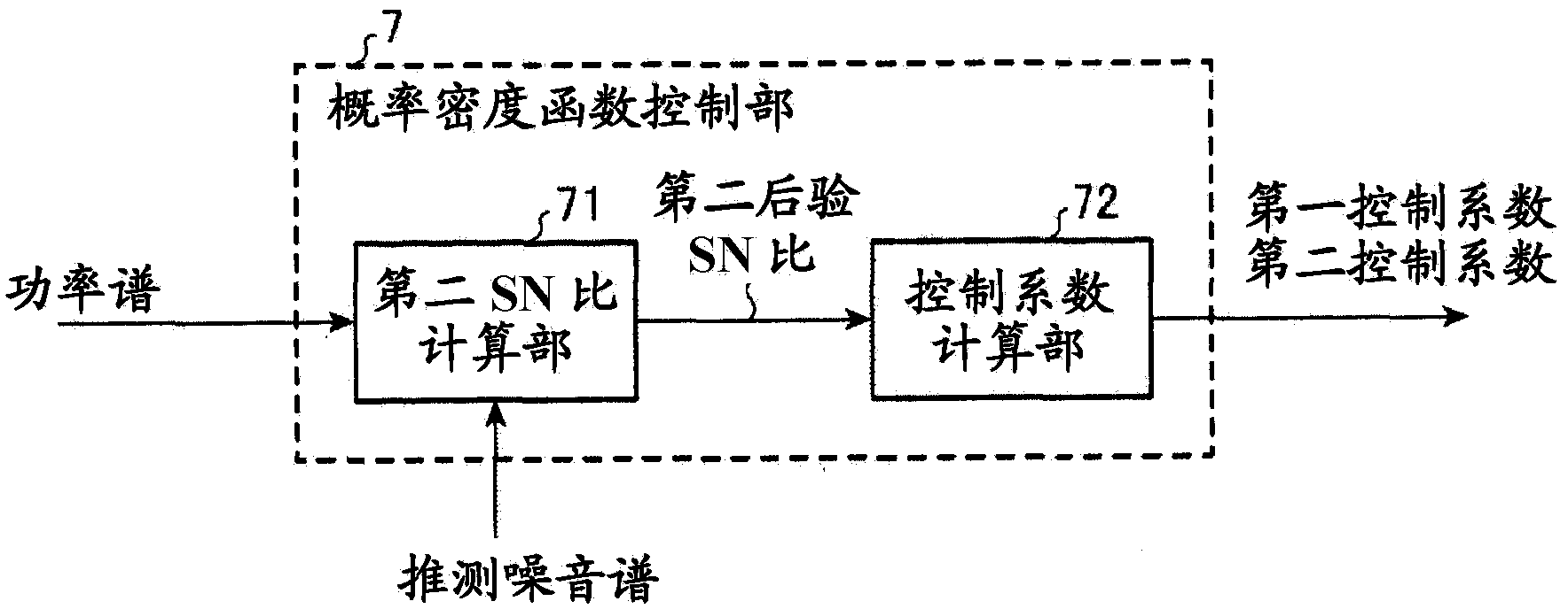
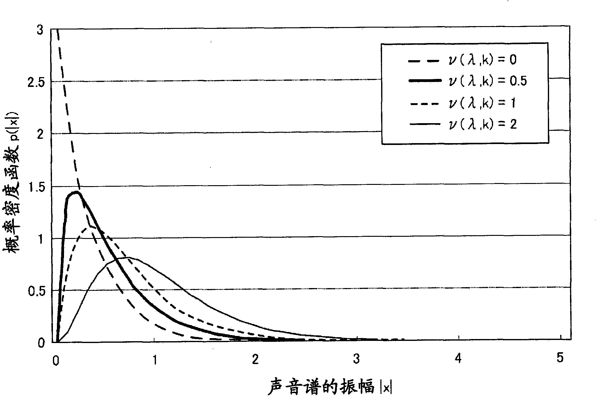
[0031] figure 1 It is a block diagram showing the overall configuration of the noise suppressing device according to the first embodiment. The noise suppression device according to Embodiment 1 includes an input terminal 1, a Fourier transform unit 2, a power spectrum calculation unit 3, a sound / noise interval determination unit 4, a noise spectrum estimation unit 5, an S / N ratio calculation unit 6, and a probability density function control unit 7 , a suppression amount calculation unit 8 , a spectrum suppression unit 9 , an inverse Fourier transform unit 10 , and an output terminal 11 .
[0032] Hereinafter, the operating principle of the noise suppression device will be described with reference to the drawings.
[0033] First, after A / D (analog / digital) conversion is performed on voice, music, etc. taken in through a microphone (not shown), etc., sampling is performed at a predetermined sampling frequency (for example, 8kHz), and (eg, 10 ms) is divided and input to the no...
Embodiment approach 2
[0094] In Embodiment 1 described above, the probability density function corresponding to the pattern of the input signal was controlled by using the a posteriori SN ratio, but it is also possible to weight the a posteriori SN ratio, for example. The purpose of this is to weight the frequency bands in which there is a high probability of the presence of sound so that the posterior SN ratio becomes higher even though the SN ratio is low despite the presence of sound, such as when the sound signal is drowned by noise. Correction to prevent false suppression of acoustic signals buried by noise.
[0095] Figure 4 is a block diagram showing the overall configuration of the noise suppressing device according to Embodiment 2, Figure 5 It is a block diagram showing the internal structure of the probability density function control part 7a among them. Figure 4 The shown probability density function control unit 7a inputs the power spectrum Y(λ, k) of the power spectrum calculation...
Embodiment approach 3
[0133] In the formula (18) of the above-mentioned Embodiment 3, the weighted value (weighting constant w p (k), w z (k)) is set to be constant in the frequency direction, but may be set to a different value for each frequency. In the weight coefficient calculation section 74, for example, as a general characteristic of sound, the harmonic structure in the low frequency band is clearer (the difference between the peak and the bottom of the spectrum is large), so the weight can be increased and decreased as the frequency becomes higher. Little weighting.
[0134] According to the third embodiment, the weight coefficient calculation unit 74 is configured to control the weighting strength of the weighted-SN ratio calculation unit 75 for each frequency, so that weighting suitable for the frequency characteristics of the sound can be performed, and higher-quality noise suppression can be performed.
PUM
 Abstract
Description
Claims
Application Information
 - R&D
- Intellectual Property
- Life Sciences
- Materials
- Tech Scout
- Unparalleled Data Quality
- Higher Quality Content
- 60% Fewer Hallucinations
Browse by: Latest US Patents, China's latest patents, Technical Efficacy Thesaurus, Application Domain, Technology Topic, Popular Technical Reports.
© 2025 PatSnap. All rights reserved.Legal|Privacy policy|Modern Slavery Act Transparency Statement|Sitemap|About US| Contact US: help@patsnap.com


