Pipe wrench

A pipe wrench and pliers head technology, applied in the field of hardware tools, can solve the problems of wasting manpower and time, the damage of the covering is large, the workers are easily injured, etc. Effect

Inactive Publication Date: 2014-10-01
张家港市星星工具制造有限公司
View PDF7 Cites 0 Cited by
  • Summary
  • Abstract
  • Description
  • Claims
  • Application Information

AI Technical Summary

Problems solved by technology

[0003] The existing straight pipe wrench generally has the handle in the middle of the tong head, but when the space around the pipe is small, such a pipe wrench needs to be twisted and repositioned many times to achieve the purpose, which wastes a lot of manpower and time, especially in the Repair some small-diameter pipes such as water pipes, and the pipes have been laid in narrow

Method used


Image

  • Pipe wrench

Examples


Example Embodiment

[0024] The present invention will be further described below in conjunction with the drawings. The following embodiments are only used to explain the technical solutions of the present invention more clearly, and cannot be used to limit the protection scope of the present invention.

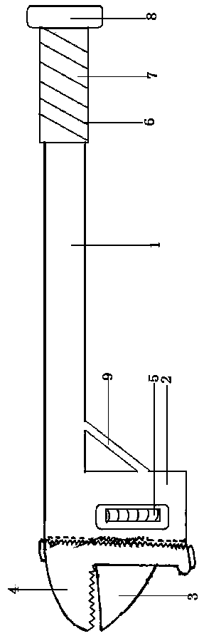
[0025] Such as figure 1 As shown, a pipe wrench is composed of a handle 1 and a clamp head 2. The clamp head 2 is composed of movable jaws 3, fixed jaws 4, and a sliding structure 5. The movable jaws 3 are connected to the main body of the clamp head 2 through the sliding structure 5 It is connected with the fixed jaw 4, and the handle 1 is located on the side of the jaw 2 and connected with the end of the jaw 1.

[0026] In the described pipe wrench, the fixed jaw 4 has jaws. The teeth of the forceps are serrated.

[0027] In the described pipe wrench, the clamp head 2 is a straight-nose clamp head.

[0028] In the described pipe wrench, the handle 1 and the clamp head 2 are provided with reinforcing...


PUM


Abstract

The invention provides a pipe wrench. The pipe wrench is composed of a handle and a wrench head. The wrench head is composed of a movable wrench jaw, a fixed wrench jaw and a sliding structure, wherein the movable wrench jaw is connected with the main body of the wrench head through the sliding structure and matched with the fixed wrench jaw; the handle is arranged on one side of the wrench head and connected with the tail end of the wrench head. The pipe wrench is wide in single twisting range and is particularly applicable to maintenance of laid small-diameter pipes.

Description

[0001] technical field [0002] The invention relates to a hardware tool, in particular to a pipe wrench. Background technique [0003] The existing straight pipe wrench generally has the handle in the middle of the tong head, but when the space around the pipe is small, such a pipe wrench needs to be twisted and repositioned many times to achieve the purpose, which wastes a lot of manpower and time, especially in the Repair some small-diameter pipes such as water pipes, and the pipes have been laid in narrow pipe grooves. When the range of activities of the pipe wrench is small, it is necessary to open the covering around the pipes in a large area during operation, which is likely to cause large damage to the covering. Repair The cost is high, and the jaws are constantly adjusted at the same time, which wastes time, because the space is small, and workers are also prone to injury. Contents of the invention [0004] Purpose of the invention: In view of the above problems,...

Claims


Application Information

Patent Timeline
IPC IPC(8): B25B13/50
CPCB25B13/5058
Inventor 卞建卫
Owner 张家港市星星工具制造有限公司
Why Eureka
Try Eureka