

Adjusting device for distance and passing light shapes of automobile head light
A technology of automobile headlights and adjustment devices, which is applied in the directions of signal devices, optical signals, vehicle components, etc., can solve the problems of large space and size, and achieve the effect of compact structure
- Summary
- Abstract
- Description
- Claims
- Application Information
AI Technical Summary
Problems solved by technology
Method used
Image

Examples
Embodiment Construction
[0023] The present invention will be described in further detail below in conjunction with the accompanying drawings.
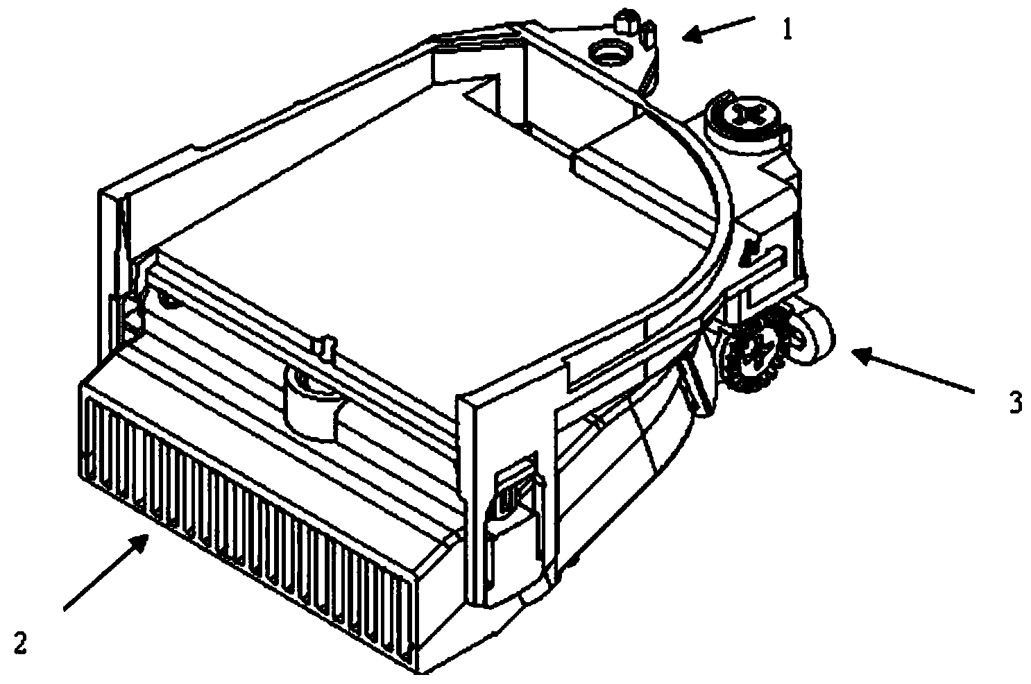
[0024] Such as figure 1 As shown, 1 is the fixed bracket, 2 is the adjusted component, and 3 is the adjustment mechanism.
[0025] The far and near beam shape adjustment device for automobile headlamps of the present invention includes a fixed bracket 1, an adjusted component 2 and an adjustment mechanism 3, the fixed bracket 1 is fixedly connected to the low beam unit, and the adjusted component 2 is fixedly connected to the far The light unit adjusts the adjusted components through the adjustment mechanism to adjust the relative position of the brightest point of the high beam unit relative to the light shape of the low beam, and then adjusts the angle between the fixed bracket and the lamp body to realize the light shape of the high beam and the light shape of the low beam. Synchronous adjustment of light and light shape.
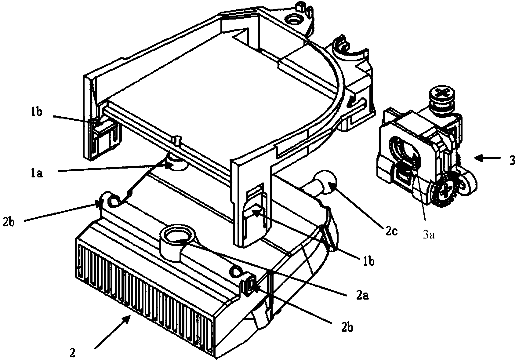
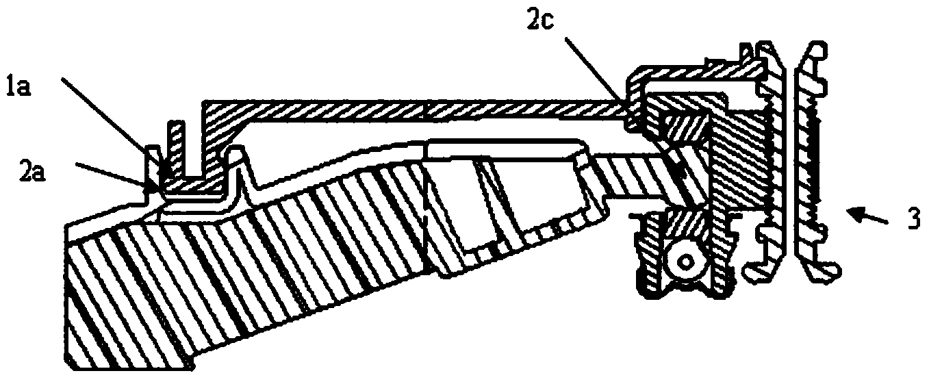
[0026] Such as Figure 2 ~ Fi...
PUM
 Abstract
Description
Claims
Application Information