Flush toilet apparatus

A toilet and flushing technology, applied in flushing toilets, water supply devices, urinals, etc., can solve problems such as residues, obstruction of smooth water flow in drainage pipelines, and inability to discharge suspended dirt

Active Publication Date: 2014-10-01
TOTO LTD
View PDF8 Cites 13 Cited by
  • Summary
  • Abstract
  • Description
  • Claims
  • Application Information

AI Technical Summary

Problems solved by technology

[0004] However, in the flush toilets of the aforementioned Patent Document 1 and Patent Document 2, since the main flow discharged from the inner edge spout and flows from the front to the rear suddenly rushes into the introduction pipe, the speed of the rear area of ​​the introduction pipe changes. Fast, on the other hand, the speed of the washing water flowing into the front side of the introduction pipe becomes slow, and sediment occurs in the front side area, so the smooth flow of water in the drain pipe is hindered
In this way, when the water flow in the drainage pipeline is blocked and the velocity distribution in the front area and the rear area is uneven (velocity distribution is not the same), there will be small-sized dirt and suspended dirt that cannot be discharged and remain in the stagnant water. question
[0005] In addition, in order to solve the problem of small-sized dirt and suspended dirt remaining, as shown in Patent Document 3, although it is also conceivable to concentrate small-sized dirt and the like in the center of the ponded water by improving the swirlability of the ponded water, in this case In this case, the problem cannot be effectively solved because small dirt and the like just swirl together with the stagnant water and do not enter the drainage pipe.

Method used


Image

  • Flush toilet apparatus
  • Flush toilet apparatus
  • Flush toilet apparatus

Examples


Embodiment Construction

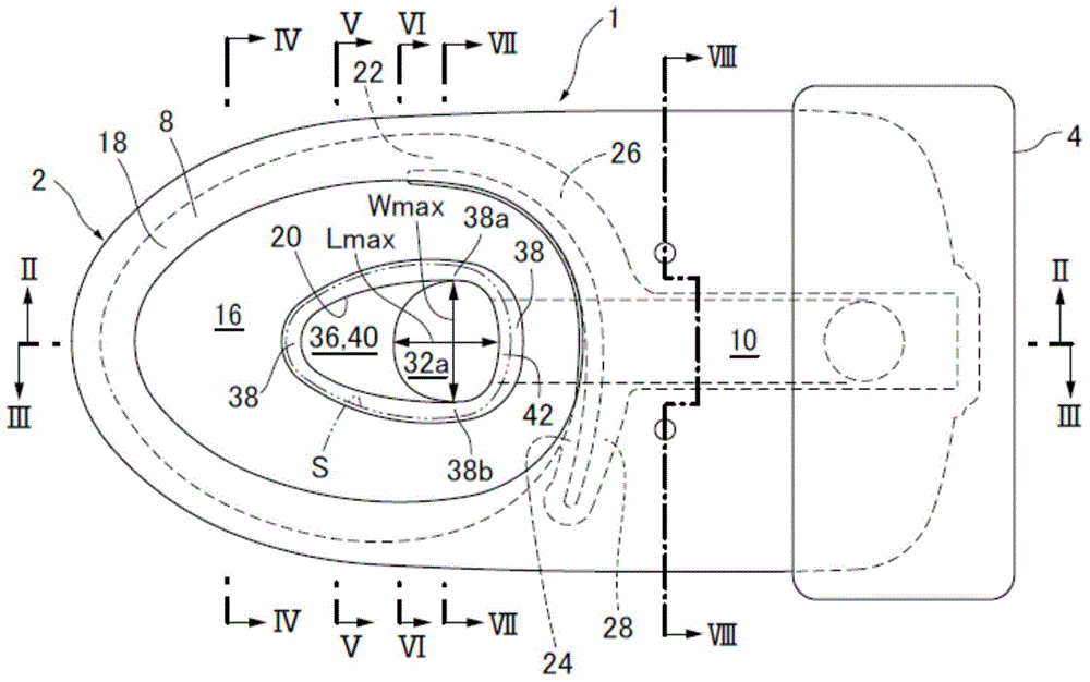
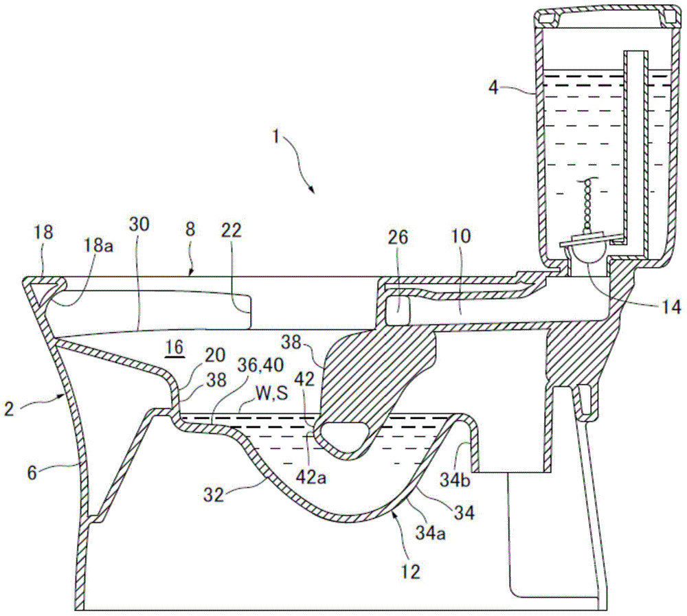
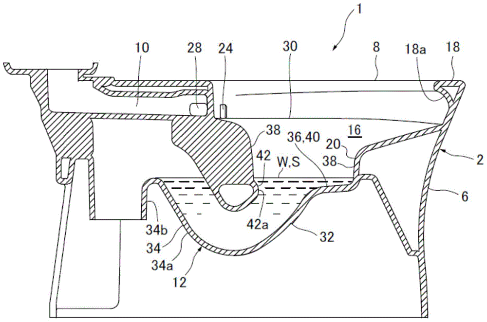
[0048] Below, refer to Figure 1 to Figure 8 , the flush toilet according to the embodiment of the present invention will be described. figure 1 It is a top view showing the flush toilet according to the embodiment of the present invention. figure 2 is along figure 1 A cross-sectional view viewed along the line II-II. image 3 is along figure 1 Cross-sectional view viewed along line III-III.

[0049] The flush toilet 1 according to the embodiment of the present invention is a floor drain type flush toilet in which a drain trap line described later is connected to a drain pipe (not shown) installed on the floor. and, Figure 4 is along figure 1 A cross-sectional view of the IV-IV line observation, Figure 5 is along figure 1 A cross-sectional view of the V-V line observation, Image 6 is along figure 1 A cross-sectional view of the VI-VI line observation, Figure 7 is along figure 1 A sectional view viewed along line VII-VII, Figure 8 is along figure 1 Cross-sec...


PUM


Abstract

A flush toilet which including a bowl portion having a waste-receiving surface, a rim and a recess; a water spouting portion for spouting the flush water forwardly; and a drainage conduit. The recess of the bowl portion has a bottom below a pooled water level, and a wall surface connecting between the bottom and a lower edge of the waste-receiving surface, wherein the bottom of the recess has a front bottom surface and a rear bottom surface. The bowl portion is configured to allow flush water to form a major stream which is directed to flow from an front end of the bowl portion toward the inlet of the drainage conduit, and the rear bottom surface of the bottom is configured to allow a part of the major stream to collide therewith, and then guide the collided major stream to a front region inside the drainage conduit.

Description

technical field [0001] The invention relates to a flush toilet, in particular to a flush toilet capable of reliably discharging small-sized dirt and suspended dirt. Background technique [0002] In the past, for example, as described in Japanese Patent Application Laid-Open No. 2011-157738 (Patent Document 1) or Japanese Patent Laid-Open No. 2011-174363 (Patent Document 2), there is known a flush toilet in which the The washing water spouted from the edge spout (first outflow port) swirls along the inner edge water channel, and the main flow flows from the front of the basin to the inlet of the drain pipe (elbow) towards the rear to discharge the waste. In this flush toilet, in order to facilitate the flushing of flush water into the inlet of the drain line, an introduction line that opens upward and extends rearward and downward is provided. [0003] In addition, as described in Japanese Patent Application Laid-Open No. 7-310352 (Patent Document 3), there is also known a f...

Claims


Application Information

Patent Timeline
Patent Type & Authority Applications(China)
IPC IPC(8): E03D11/08E03D11/13E03D11/17
CPCE03D11/08E03D2201/40
Inventor 平河智博北村正树头岛周篠原祐纪龟井浩志
Owner TOTO LTD
Why Eureka
Try Eureka