Perforation processing device and processing method for perforated processing waste of cornertube

A technology of processing device and processing method, which can be used in perforating tools, peeling devices, metal processing equipment, etc., to solve the problems of limited quantity, inability to apply, adhesion to the inside of lifting parts or pipes, etc., to achieve the effect of prolonging life.

Active Publication Date: 2018-06-26
NISSHINBO MECHATRONICS
View PDF9 Cites 0 Cited by
  • Summary
  • Abstract
  • Description
  • Claims
  • Application Information

AI Technical Summary

Problems solved by technology

This method has the following disadvantages: the storage capacity of waste materials is limited, and the number of holes for perforation processing is limited
[0010] The second prior art is the method without a cover in the inner mold assembly
This method has the following disadvantage: when the piercing process is performed continuously, the scrap inside the pipe does not move a distance corresponding to the movement amount of the pipe according to its inertia when the pipe moves, and thus becomes in a state of retreating relative to the inner surface of the pipe
This method has the following disadvantages: when the passage from the bottom of the blade of the punch to the position where the air is discharged is long, the vacuum effect cannot be generated, and when the distance from the perforated surface to the waste storage surface is as short as 16mm , does not produce a vacuum effect, and the waste gas from the containing part may adhere to the inside of the lifting part or the pipe
This method has the following disadvantages: because the through hole is provided on the punch, the blade of the punch becomes thinner, so it cannot be applied to the edge of a narrower width corner hole or a punch with a small diameter

Method used


Image

  • Perforation processing device and processing method for perforated processing waste of cornertube
  • Perforation processing device and processing method for perforated processing waste of cornertube
  • Perforation processing device and processing method for perforated processing waste of cornertube

Examples


Embodiment Construction

[0142] Embodiments of the present invention will be described below in conjunction with the accompanying drawings.

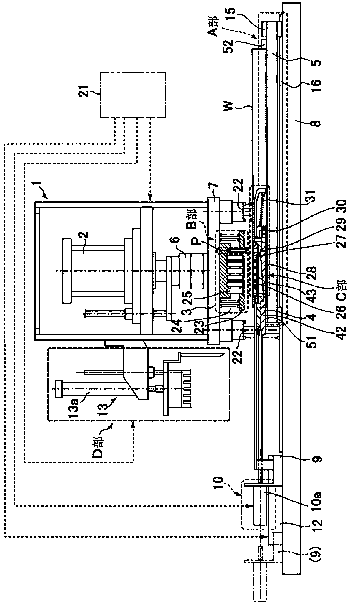
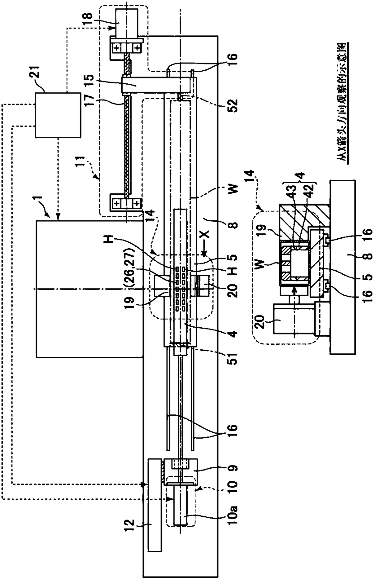
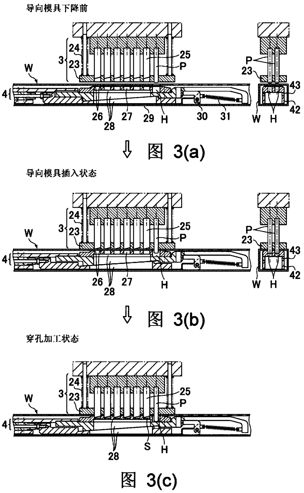
[0143] figure 1 It is an overall view (front view) of the perforating device of the first invention, and figure 2 It is an overall view (plan view) of the punching device of the first invention. Figure 3(a) ~ Figure 3(c) It is a schematic diagram of an outer mold device using a guide mold used in the piercing processing device of the first invention, Figure 4(a) ~ Figure 4(c) It is a schematic diagram of the expansion / reduction mechanism of the inner mold device used in the piercing processing device of the first invention, and Fig. 5 (a) and Fig. 5 (b) are waste recovery mechanisms of the inner mold device used in the piercing processing device of the first invention schematic diagram, Figure 6 It is an overall view (plan view) of a punching device according to another example of the first invention, Figure 7 It is an overall view (side view) of a punc...


PUM

PropertyMeasurementUnit
lengthaaaaaaaaaa

Abstract

The invention provides a method for processing a perforation processing device and perforated processing waste of a corner tube. The perforation processing device includes an outer side mold device disposed on the outer side of a tube stock, and an inner side mold device inserted into the tube stock and cooperated with a die of the outer side mold device to process the tube stock. The perforationprocessing device includes a workbench which carries the tube stock and can be positioned and moved. Relative to the outer side mold device, the workbench carrying the tube stock is moved and positioned, to perform predetermined perforation processing of the tube stock.

Description

technical field [0001] The present invention relates to a piercing device for processing a pipe material, and more particularly to a piercing device for mounting the pipe material on a movable table using an inner mold device inserted into the inside of the pipe material and an outer mold device installed outside the pipe material. processing device. [0002] In addition, the present invention relates to a piercing device for processing a pipe material, and more particularly, to a device capable of efficiently processing a hole caused by the piercing process by using an inner die device inserted into the inside of the pipe material and an outer die device provided outside the pipe material Disposal method of perforation processing waste of dregs (hereinafter referred to as "scrap"). Background technique [0003] In the prior art, when the pipe is processed such as piercing, the processing is completed through the cooperation of the inner mold device arranged inside the pipe...

Claims


Application Information

Patent Timeline
Patent Type & Authority Applications(China)
IPC IPC(8): B21D28/28B21D28/34B21D45/02
CPCB21D28/28B21D28/34B21D45/003B21D45/02
Inventor 中川洋市川道春
Owner NISSHINBO MECHATRONICS
Why Eureka
Try Eureka