
Fuel pipe for fuel injection device

A technology of fuel injection device and fuel injection valve, which is applied in the direction of fuel injection device, charging system, combustion engine, etc. It can solve the problems of fuel temperature rise, abnormal driving, easy exposure, etc., and achieve the effect of improving discharge performance

Inactive Publication Date: 2004-12-01
KEIHIN CORP
View PDF0 Cites 0 Cited by
  • Summary
  • Abstract
  • Description
  • Claims
  • Application Information

AI Technical Summary

Problems solved by technology

[0013] According to the fuel pipe used in the above-mentioned conventional fuel injection device, when the motorcycle is continuously driven in a state where the external temperature is high, the engine is temporarily stopped and then restarted, among them (at the time of hot restart), there is In the smooth restart of the engine, or immediately after the engine is started, the driving is not normal
[0014] The first reason is that the temperature of the fuel in the fuel supply pipe 18, the fuel introduction pipe 15, the fuel pipe 13, etc. increases greatly.
[0015] That is, its reason is: with respect to the machine that the engine of motorcycle etc. is directly exposed, fuel pipe 18, fuel inlet pipe 15, fuel pipe 13 are easily directly affected by heat radiation from the engine after the engine stops; 18, 15, 13 Direct exposure to the atmosphere, easy exposure to outside air temperature, direct sunlight
[0016] The second reason is that the fuel pipe 18, the fuel inlet pipe 15, and the fuel pipe 13 are closed and connected to the fuel injection valve J.
[0019] In addition, in the state described above, if the engine is restarted, or the engine is driven immediately after the engine is started, the fuel pressure is lowered due to the steam contained in the fuel, or the amount of injected fuel discharged toward the engine is further increased in an intermittent manner. As a result, the startability of the engine deteriorates, or the driving is not normal immediately after starting

Method used


Image

  • Fuel pipe for fuel injection device
  • Fuel pipe for fuel injection device
  • Fuel pipe for fuel injection device

Examples


Embodiment Construction

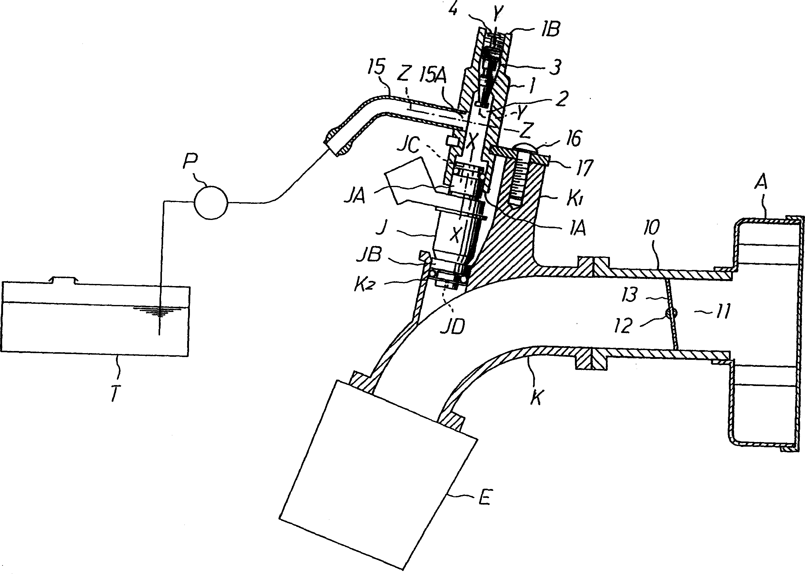
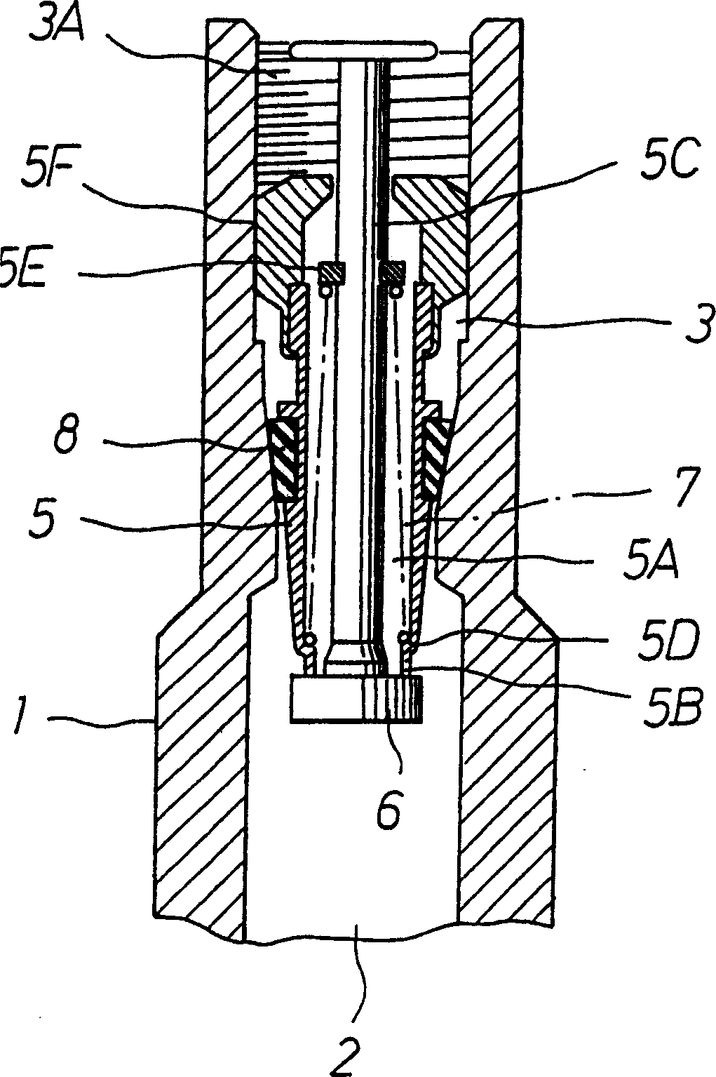
[0034] pass below figure 1 One embodiment of the fuel pipe of the fuel injection device of the present invention will be described. This embodiment is a fuel injection device having a single fuel injection valve for the engine, and descriptions of the same parts as in FIG. 4 are omitted by using the same symbols.

[0035] A fuel flow path 2 is opened in the fuel pipe 1 in the vertical direction, and the fuel flow path 2 opens toward the bottom end 1A of the fuel pipe 1 downward in the direction of gravity.

[0036] In addition, an opening 15A of a fuel introduction pipe 15 connected to the fuel pump P is opened in the middle of the fuel flow path 2 , and the fuel flow path 2 is opened upward in the direction of gravity through the atmosphere opening passage 3 to the atmosphere.

[0037]In other words, the lower part of the fuel flow path 2 is opened at the bottom end 1A of the fuel pipe 1, the upper part of the atmosphere opening passage 3 communicating with the fuel flow pat...


PUM


Abstract

A fuel pipe (1) is provided inside with a fuel flow passage (2), a fuel inflow hole (JC) of a fuel injection valve (J) is open to the lower side of the fuel flow passage (2) in a gravitational direction, an opening portion (15A) of a fuel introduction pipe (15) connected to a fuel pump (P) is open to the fuel flow passage (2) at an upper position in the gravitational direction than a fuel inflow hole (JC), an atmospheric air releasing passage (3) is open to and connected to an uppermost position of the fuel flow passage (2) in the gravitational direction, and the atmospheric air releasing passage (3) is opened and closed by a normally closed type shut-off valve (4).

Description

technical field [0001] The present invention relates to a fuel injection device, which raises the pressure of the fuel in the fuel tank through a fuel pump, and supplies the boosted fuel to an internal combustion engine through a fuel injection valve, wherein the present invention particularly relates to a motor vehicle suitable for being installed on a motorcycle, a small Fuel pipes for fuel injection devices on trucks, outboard motors, general purpose motors, etc. Background technique [0002] Next, a fuel pipe of a conventional fuel injection device will be described with reference to FIG. 4 . [0003] 10 represents a throttle valve body penetrating through the side of the internal intake passage 11. The intake passage 11 is opened and closed by a butterfly throttle valve 13, which is mounted on a rotatably supported On the throttle body 10 is a throttle lever 12 which is operated by an operator. [0004] In addition, the air cleaner A is connected to the upstream side ...

Claims


Application Information

Patent Timeline
Patent Type & Authority Applications(China)
IPC IPC(8): F02M55/00
CPCY02T10/123Y02T10/12
Inventor 小岛洋司前田邦彦佐藤清人
Owner KEIHIN CORP
Learn More