Oil pipe bridge plug

A bridge plug and oil pipe technology, applied in the field of downhole tools, can solve problems such as shortening the operation cycle, unusability, formation water lock damage, etc., and achieve the effect of shortening the operation cycle, reducing the impact, and reducing the operation cost

Active Publication Date: 2014-10-01
BC P INC CHINA NAT PETROLEUM CORP +1
View PDF6 Cites 16 Cited by
  • Summary
  • Abstract
  • Description
  • Claims
  • Application Information

AI Technical Summary

Problems solved by technology

This method has a long construction period, high operating costs, and affects the water injection effect
[0003] For some water-sensitive formations, if there is a puncture leakage on the Christmas tree during the production of oil and gas wells, if the operation method of killing the well first and then replacing the Christmas tree hanger is used, it will cause water lock damage to the formation after operation. , Oil and gas wells are severely reduced or shut down
[0004] The existing blockage tools in the tubing either cannot be used under pressure at the wellhead, or cannot be pulled out smoothly after installation, and production can be resumed directly
In short, the existing tools and operating methods cannot meet the requirements of shortening the operating cycle, reducing operating costs, and reducing the impact of operations on the formation

Method used


Image

  • Oil pipe bridge plug
  • Oil pipe bridge plug

Examples


Embodiment Construction

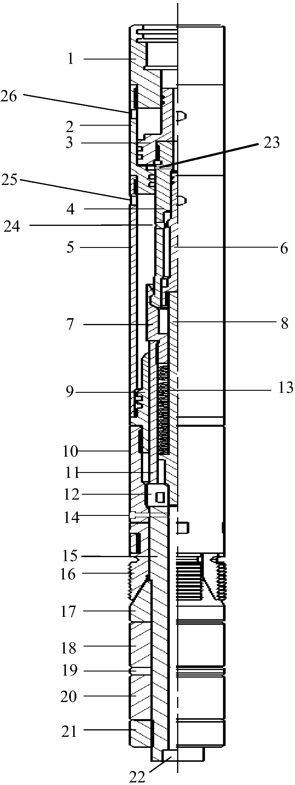
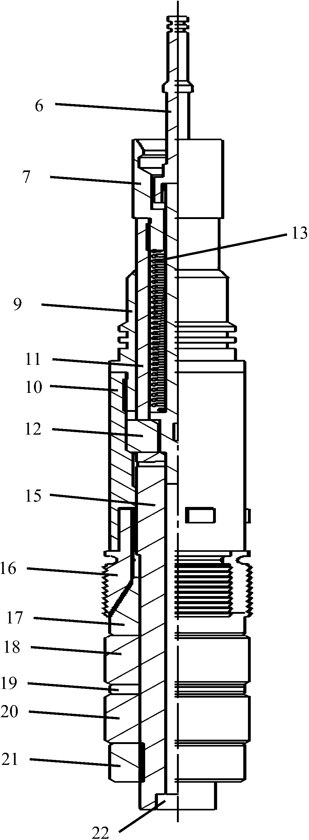
[0013] Below in conjunction with accompanying drawing and specific embodiment the present invention is described in further detail:

[0014] Such as figure 1 , 2 As shown, the oil pipe bridge plug of the present invention includes an upper joint 1, a piston cylinder 2, a boss-shaped piston 3, an upper throwing hand 4, an upper casing 5, a sealing push rod 6, a lower throwing hand 7, a lock cylinder 8, and a fishing head 9. Slip seat 10, upper center tube 11, lower center tube 15, lock block 12, spring 13, setting shear nail 14, slip 16, cone 17, sealing rubber tube, steel spacer ring 19, locking Ring 21, plug 22; the upper end of the upper joint 1 is connected with the delivery pipe through the internal thread, and the lower end is connected with the internal thread at the upper end of the piston cylinder 2 through the external thread; the upper part of the piston cylinder 2 has a pressure relief hole 26, and the external thread at the lower end is connected with the upper sh...


PUM


Abstract

The invention discloses an oil pipe bridge plug, which is used for packing fluid and pressure in upper and lower spaces inside an oil pipe to realize the operation of changing a production tree upper hanging element with pressure. The oil pipe bridge plug mainly consists of two parts including a sealing mechanism and a setting releasing handle mechanism, wherein the sealing mechanism is a part remained in the oil pipe after the bridge plug plugging for achieving the packing effect, and comprises components including a center pipe, a lower releasing handle head, a fishing head, a sealing rod, a lock core, a lock block, a spring, a lower casing, a setting shear pin, a one-way slip, a cone body, a sealing rubber tube, a rubber tube retainer, a back cap and the like. The setting releasing handle mechanism is a part for enabling the bridge plug to complete the setting action and realizing the handle releasing, and comprises components including an upper joint, a piston cylinder, an upper casing, a setting piston, an elastic lifting clamp claw, an upper releasing handle head and the like. The oil pipe bridge plug is conveyed into the oil pipe through the hollow rod; through the pressurization into the center pipe, the piston generates ascending thrust, and the center pipe and the lock block are driven to upwards move; and the actions of rubber tube compression, slip anchoring, setting state locking, handle releasing and the like are realized. The oil pipe bridge plug is used for packing the upper and lower spaces of the oil pipe under pressure and achieving the goal of changing the production tree upper hanging element with pressure.

Description

technical field [0001] The invention relates to a downhole tool used in the development and application of oil and gas fields, in particular, it is suitable for replacing the oil pipe bridge plug of the oil pipe hanging on the Christmas tree under pressure in water injection wells hanging on the Christmas tree and in water-sensitive formations. Background technique [0002] The wellhead pressure of water injection wells is generally around 30MPa. If there is a puncture on the Christmas tree during water injection, the current practice is to release the pressure in the open well for a period of time. After the wellhead pressure decreases, use the hydraulic well to kill the well, and finally replace the Christmas tree. Hang on. This method has a long construction period, high operating costs, and affects the water injection effect. [0003] For some water-sensitive formations, if there is a puncture leakage on the Christmas tree during the production of oil and gas wells, if ...

Claims


Application Information

Patent Timeline
Patent Type & Authority Applications(China)
IPC IPC(8): E21B33/134
Inventor 王玉忠马金良黄德辉
Owner BC P INC CHINA NAT PETROLEUM CORP
Why Eureka
Try Eureka