Cryopump and method for evacuation

A cryopump and cryopanel technology, applied in pumps, liquid variable capacity machinery, machines/engines, etc., can solve the problem that cryopumps cannot fully function, and achieve the effect of increasing gas retention

Active Publication Date: 2014-10-01
SUMITOMO HEAVY IND LTD
View PDF8 Cites 3 Cited by
  • Summary
  • Abstract
  • Description
  • Claims
  • Application Information

AI Technical Summary

Problems solved by technology

After that, the cryopump will not be able to fully play its original role

Method used


Image

  • Cryopump and method for evacuation
  • Cryopump and method for evacuation
  • Cryopump and method for evacuation

Examples


Embodiment Construction

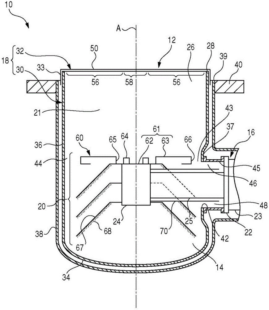
[0016] figure 1 It is a side cross-sectional view schematically showing main parts of the cryopump 10 according to the first embodiment of the present invention. The cryopump 10 is installed in, for example, a vacuum chamber of an ion implantation device or a sputtering device, and is used to increase the degree of vacuum inside the vacuum chamber to a level required for a desired process. The cryopump 10 has a suction port 12 for receiving gas. The gas to be exhausted enters the inner space 14 of the cryopump 10 from the vacuum chamber in which the cryopump 10 is installed through the suction port 12 . figure 1 A cross section including the central axis A of the inner space 14 of the cryopump 10 is shown.

[0017] In addition, terms such as “axial direction” and “radial direction” may be used below in order to facilitate understanding of the positional relationship of the components of the cryopump 10 . Axial represents the direction through the suction port 12 ( figure 1...


PUM


Abstract

The invention provides a cryopump and a method for evacuation. A cryopump(10) includes a refrigerator (16), a first cryopanel(18) including a radiation shield(30) and a plate member across a shield opening and a second cryopanel(20) enclosed by the first cryopanel(18) and cooled to a lower temperature than that of the first cryopanel(18) . The refrigerator (16) is disposed on the radiation shield(30). The shield member is adjacent to an installation pedestal(37), and is used to enclose the second cryopanel(20). The lateral gap (43) can be formed between the second cryopanel(20)and the installation pedestal (37). The gap part (44) connected to the lateral gap (43) is formed between the second cryopanel(20) and the shield member. The shape of the second cryopanel(20) or the second cryopanel(20) is configured to be consistent to the width of the later gap (43) and the width of the gap part (44).

Description

[0001] This application claims priority based on Japanese Patent Application No. 2013-062560 filed on March 25, 2013 and Japanese Patent Application No. 2013-125819 filed on June 14, 2013. The entire contents of these Japanese patent applications are incorporated herein by reference. technical field [0002] The invention relates to a cryopump. Background technique [0003] A cryopump generally includes two types of cryopanels with different temperatures. The gas condenses on a cold cryopanel. With the use of the cryopump, the condensed layer gradually grows on the low-temperature cryopanel, and may soon come into contact with the high-temperature cryopanel. In this way, at the contact portion between the high-temperature cryopanel and the condensed layer, the gas is vaporized again and released to the surroundings. After that, the cryopump will not be able to fully play its original role. Therefore, the storage amount of gas at this time becomes the maximum storage amou...

Claims


Application Information

Patent Timeline
Patent Type & Authority Applications(China)
IPC IPC(8): F04B37/08
CPCF04B37/08
Inventor 及川健
Owner SUMITOMO HEAVY IND LTD
Why Eureka
Try Eureka