A hydraulic booster energy recovery system and control device

A pressurization energy recovery system technology, applied in fluid pressure actuation devices, fluid pressure actuation system components, fluid pressure converters, etc., can solve problems such as cost increase, energy waste, and insufficient number of pressurization times, and achieve Reduce excessive inertia and hydraulic shock, reduce cost, and facilitate structure

Inactive Publication Date: 2016-08-03
QINGDAO UNIV
View PDF3 Cites 0 Cited by
  • Summary
  • Abstract
  • Description
  • Claims
  • Application Information

AI Technical Summary

Problems solved by technology

[0002] In the hydraulic system, after the actuators such as hydraulic cylinders and hydraulic motors operate, they usually discharge low-pressure oil, especially in engineering machinery with large potential energy such as excavating machinery, loading machinery and lifting equipment, some of these equipment Actuating components such as excavating arms and booms usually have a large potential energy when they are lowered. This potential energy will prompt the actuators of the hydraulic system to discharge a large amount of low-pressure oil. If the low-pressure oil cannot be fully utilized and directly flows back to the oil tank, then The energy of these low pressure fluids will be wasted
[0003] In addition, when the rated pressure of the system is low, individual components that require high pressure often need to be supplied with a separate high-pressure pump, and the additional high-pressure pump not only increases the volume of the system, but also increases the cost
[0004] Traditional hydraulic boosters generally only have one boosting stroke, that is, boosting can only be achieved when the piston moves in one direction, and boosting cannot be achieved when the piston returns. In the same time, the number of boosting times is not enough

Method used


Image

  • A hydraulic booster energy recovery system and control device

Examples


Embodiment Construction

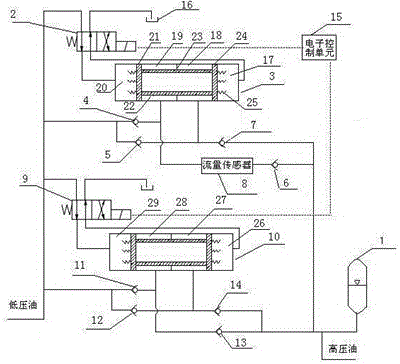
[0024] In the figure, 1. accumulator, 2. first solenoid valve, 3. first hydraulic booster, 4. first check valve, 5. second check valve, 6. third check valve, 7 , the fourth one-way valve, 8, the flow sensor, 9, the second solenoid valve, 10, the second hydraulic booster, 11, the fifth solenoid valve, 12, the sixth solenoid valve, 13, the seventh solenoid valve, 14 , the eighth solenoid valve, 15, the electronic control unit, 16, the oil tank, 17, the low-pressure chamber on the right side of the first hydraulic booster, 18, the high-pressure chamber on the right side of the first hydraulic booster, 19, the first hydraulic booster Left side high-pressure chamber, 20, left side low-pressure chamber of the first hydraulic booster, 21, left side piston head, 22, piston rod, 23, sub-cavity layer, 24, right side piston head, 25, spring, 26, the first Second hydraulic booster right side low-pressure chamber, 27, the second hydraulic booster right side high-pressure chamber, 28, the s...


PUM


Abstract

A hydraulic pressure boost energy recovery system and control device, wherein the hydraulic pressure boost energy recovery system has two groups, the first group consists of a first solenoid valve, a first hydraulic pressure booster, a first one-way valve, a second one-way valve, the third one-way valve, the fourth one-way valve, the second group consists of the second solenoid valve, the second hydraulic booster, the fifth one-way valve, the sixth one-way valve, the seventh one-way valve, the It is composed of eight one-way valves; the control device of the hydraulic booster energy recovery system includes an electronic control unit and a flow sensor; the rest of the hydraulic devices include an accumulator and a fuel tank. The low-pressure oil passes through the first pressure booster and the second pressure booster, and is transformed into high-pressure oil and stored in the accumulator to complete the recovery of pressurized energy. The electronic control unit adjusts the working positions of the first solenoid valve and the second solenoid valve to be opposite according to the signal of the flow sensor, and controls the movement direction of the first pressure booster and the second pressure booster to be opposite to avoid hydraulic shock.

Description

technical field [0001] The invention relates to a hydraulic boosting energy recovery system and a control device, in particular to a device for boosting low-pressure oil in a hydraulic system and collecting energy for the boosted oil. Background technique [0002] In the hydraulic system, after the actuators such as hydraulic cylinders and hydraulic motors operate, they usually discharge low-pressure oil, especially in engineering machinery with large potential energy such as excavating machinery, loading machinery and lifting equipment, some of these equipment Actuating components such as excavating arms and booms usually have a large potential energy when they are lowered. This potential energy will prompt the actuators of the hydraulic system to discharge a large amount of low-pressure oil. If the low-pressure oil cannot be fully utilized and directly flows back to the oil tank, then The energy of these low-pressure oils will be wasted. [0003] In addition, when the rat...

Claims


Application Information

Patent Timeline
Patent Type & Authority Patents(China)
IPC IPC(8): F15B3/00F15B21/14
Inventor 张震
Owner QINGDAO UNIV
Why Eureka
Try Eureka