Optical scanning device and image forming device including optical scanning device

An optical scanning device and deflection scanning technology, which are applied in optics, optical components, and electrical recording process applying charge patterns, etc., can solve the problems of reduced image quality of printed images and large heating of the driving IC, and achieve the purpose of suppressing the tipping of the axis, effectively cooling effect

Inactive Publication Date: 2016-06-01
KYOCERA DOCUMENT SOLUTIONS INC
View PDF3 Cites 0 Cited by
  • Summary
  • Abstract
  • Description
  • Claims
  • Application Information

AI Technical Summary

Problems solved by technology

[0004] In the above-mentioned optical scanning device, if the polygon mirror motor is operated at high speed, the heat generated from the driver IC becomes excessive, and as a result, there is a problem that the optical lens is thermally deformed and the image quality of the printed image is lowered.

Method used


Image

  • Optical scanning device and image forming device including optical scanning device
  • Optical scanning device and image forming device including optical scanning device
  • Optical scanning device and image forming device including optical scanning device

Examples


Embodiment Construction

[0033] Hereinafter, embodiments of the present invention will be described in detail based on the drawings. In addition, this invention is not limited to the following embodiment.

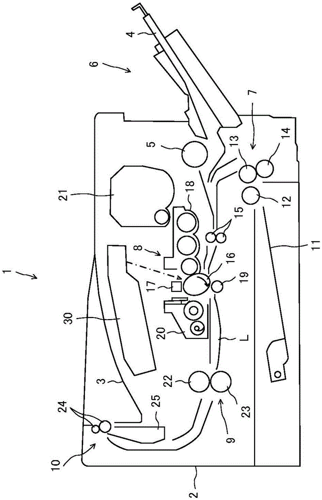
[0034] figure 1 It is a cross-sectional view showing a schematic configuration of a laser printer as an image forming apparatus according to the present embodiment.

[0035] Such as figure 1 As shown, the laser printer 1 includes a box-shaped printer body 2 , a manual paper feeder 6 , a cassette paper feeder 7 , an image forming unit 8 , a fixing unit 9 , and a paper discharge unit 10 . The laser printer 1 transports paper along a transport path L inside the printer body 2 and forms an image on the paper based on image data transmitted from a terminal not shown.

[0036] The manual feed unit 6 has a manual tray 4 and a feed roller 5 . The manual tray 4 is provided on one side of the printer main body 2 so as to be openable and closable. The paper feed roller 5 is a roller for manual paper feed...


PUM


Abstract

An optical scanning device includes a rotating polygon mirror, a motor, a substrate, a heat releasing member and a heat transfer member. The rotating polygon mirror deflection scans light emitting by a light source. The motor rotatively drives the rotating polygon mirror. The substrate has a drive circuit part for controlling the motor. The heat releasing member releases heat generated from the substrate. The heat transfer member is sandwiched between the substrate and the heat releasing member to be compressively deformed. A receiving portion that part of the heat transfer member compressively deformed enters is formed in a first part of the heat releasing member in which the heat transfer member is provided.

Description

technical field [0001] The present invention relates to an optical scanning device and an image forming device including the optical scanning device. Background technique [0002] There is known an optical scanning device used in an electrophotographic image forming apparatus such as a laser printer, in which laser light emitted from a light source is reflected and deflected by a polygon mirror rotating at high speed. The laser light reflected by the polygon mirror passes through the optical lens and scans the surface of the photosensitive drum. [0003] This optical scanning device includes a polygon mirror motor, a driver IC, and a substrate. The polygon mirror motor drives the polygon mirror to rotate. The driver IC is an IC (Integrated Circuit) for driving a polygon mirror motor. A driver IC is mounted on the substrate, and a bearing hole for receiving the rotation shaft of the polygon mirror motor is formed. [0004] In the above-mentioned optical scanning device, i...

Claims


Application Information

Patent Timeline
Patent Type & Authority Patents(China)
IPC IPC(8): G03G15/04G02B26/12
CPCB41J2/471
Inventor 平川宏之
Owner KYOCERA DOCUMENT SOLUTIONS INC
Why Eureka
Try Eureka