Liquid-ring vacuum pump, and impeller for a liquid-ring vacuum pump

A liquid ring vacuum pump and impeller technology, applied in the direction of pumps, rotary piston pumps, mechanical equipment, etc., can solve problems such as unfiltered

Active Publication Date: 2014-10-01
斯特林工业咨询有限公司
View PDF10 Cites 2 Cited by
  • Summary
  • Abstract
  • Description
  • Claims
  • Application Information

AI Technical Summary

Problems solved by technology

[0007] One disadvantage of impellers having high strength is that during operation of the pump, the shaking loads experienced by the impeller

Method used


Image

  • Liquid-ring vacuum pump, and impeller for a liquid-ring vacuum pump
  • Liquid-ring vacuum pump, and impeller for a liquid-ring vacuum pump
  • Liquid-ring vacuum pump, and impeller for a liquid-ring vacuum pump

Examples


Embodiment Construction

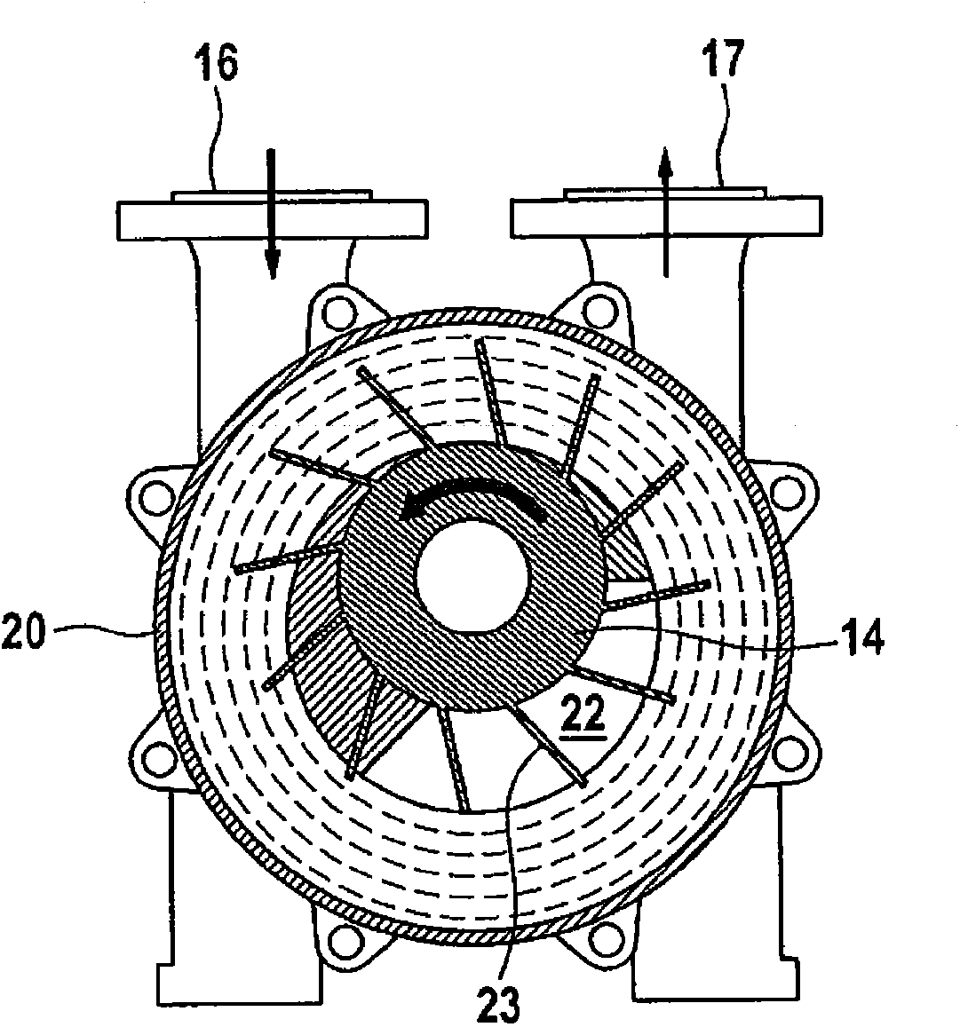
[0021] exist figure 1 In the liquid ring vacuum pump shown, the impeller 14 is mounted eccentrically in the pump housing 20 . The liquid inside the pump is driven by the rotating impeller 14 and forms a liquid ring extending radially inward from the outer wall of the pump casing 20 . Due to the eccentric mounting, the blades of the impeller 14 protrude into the liquid ring to different depths depending on the angular position. The volume of the chamber 22 enclosed between the two vanes thus changes. The liquid ring thus acts as a piston which moves up and down in the chamber during the revolution of the impeller 14 .

[0022] From the inlet 16 a tube leads into the interior of the pump in which the impeller 14 rotates. The tubes open in the region where the blades of the impeller 14 emerge from the liquid ring, in which region the chamber enclosed between the two blades thereby widens. Due to the enlarged chamber, gas is sucked into the chamber through the inlet 16 . Afte...


PUM

PropertyMeasurementUnit
Elastic modulusaaaaaaaaaa

Abstract

The invention relates to a liquid-ring vacuum pump comprising a pump casing (20) and an impeller (14) that is eccentrically mounted in the pump casing (20). According to the invention, the impeller (14) is made of a material having a modulus of elasticity of less than 4000 N/mm2. The invention further relates to an impeller (14) for such a pump. The disclosed impeller allows the pump to operate closer to the cavitation limit.

Description

technical field [0001] The invention relates to a liquid ring vacuum pump having a pump housing and an impeller mounted eccentrically in the pump housing. Furthermore, the invention also relates to an impeller for a pump of this type. This type of pump can be used to evacuate containers or other enclosed spaces. The inlet of the pump is connected to the space to be evacuated, through which the gas contained in the space is sucked in, compressed in the pump and delivered again through the outlet. Background technique [0002] In a liquid ring vacuum pump, the liquid ring is kept in motion by the impeller, with the result that the chamber between the blades of the impeller is closed by the liquid ring. Due to the eccentric mounting of the impeller in the pump casing, the liquid ring penetrates into the chamber to varying degrees depending on the angular position of the impeller and, as a result, acts as a piston changing the volume of the chamber. The impeller is a heavily ...

Claims


Application Information

Patent Timeline
IPC IPC(8): F01C21/08F04C19/00
CPCF05C2225/00F05C2225/06F05C2251/02F01C21/08F05C2225/12F04C19/00
Inventor 海纳·克斯特斯马蒂亚斯·塔姆丹尼尔·许策
Owner 斯特林工业咨询有限公司
Why Eureka
Try Eureka