
Gate auto-locking device

An automatic locking and locking device technology, which is applied in water conservancy projects, sea area projects, coastline protection, etc., can solve problems such as potential safety hazards, increased wire rope fatigue, and out-of-control gates, and achieves the effects of avoiding danger, flexible gate operation, and reasonable design

Inactive Publication Date: 2014-10-08
STATE GRID CORP OF CHINA +2
View PDF5 Cites 2 Cited by
  • Summary
  • Abstract
  • Description
  • Claims
  • Application Information

AI Technical Summary

Problems solved by technology

For the suspended gate, although there is a brake control, the gate will lose control and slide freely when the brake fails; in addition, the gate suspended in the air has a long-term load on the steel wire rope, which increases the fatigue of the steel wire rope. The above is a serious safety hazard

Method used


Image

  • Gate auto-locking device
  • Gate auto-locking device

Examples


Embodiment Construction

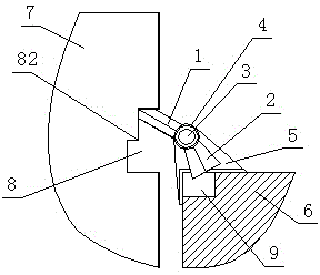
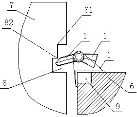
[0013] When the gate needs to be locked, the gate is lifted by the hoist. At this time, the lock is in a free state. During the rising process of the gate, the locking rod is driven to rotate around the axis. When the locking point of the gate rises above the top of the locking rod, the locking rod is symmetrical The moment of gravity of the parts is basically equal, and the locking rod swings back between the locking point and the free position. At this time, the gate falls, and the locking rod can be pressed against the locking point, and the gate is locked.

[0014] When the gate needs to be unlocked and lowered, the gate can be lifted first (greater than 200mm) until the free position is higher than the top of the locking rod. Under the action of gravity, the locking rod can resume free rotation. At this time, the gate can be lowered freely, which is the unlocking of the gate. process.


PUM


Abstract

The invention relates to a gate auto-locking device for large-sized hydropower stations or pumped storage power stations. The gate auto-locking device comprises a locking bar, a counterweight, a shaft, a shaft sleeve, and a locking support. The locking bar and the counterweight are fixed on the shaft sleeve. The shaft sleeve sleeves the shaft. The shaft is fixed on a concrete foundation through the locking base. A gate is provided with a locking slot matching with the gate auto-locking device; the locking slot is provided with a locking point at which the gate is locked and a free position at which the gate is unlocked.

Description

technical field [0001] The invention relates to a locking device for an automatic gate of a large hydropower station or a pumped storage power station. Background technique [0002] Large or heavy gates in actual operation are always open and static. For the suspended gate, although there is a brake control, the gate will lose control and slide freely when the brake fails; in addition, the gate suspended in the air has a long-term load on the steel wire rope, which increases the fatigue of the steel wire rope, which is a serious safety hazard. In order to ensure the safe operation of the gate, a locking device must be installed to lock it when the gate is not opened or closed. Contents of the invention [0003] In order to solve the above problems, the present invention provides an automatic locking device for a gate, which can ensure the safe use of the gate. [0004] The specific solution is: A gate automatic locking device, characterized in that it includes a locking ...

Claims


Application Information

Patent Timeline
IPC IPC(8): E02B7/20
Inventor 李政李涛周鹏李伟
Owner STATE GRID CORP OF CHINA
Learn More