Constant support and hanger

A support hanger and pull rod technology, applied in the field of support hangers, can solve the problems of inconvenient use and inability to adjust the length, and achieve the effects of improving convenience, improving safety, and avoiding concentrated stress

Active Publication Date: 2014-10-08
JIANGSU DALICHENG ELECTRICAL
View PDF4 Cites 6 Cited by
  • Summary
  • Abstract
  • Description
  • Claims
  • Application Information

AI Technical Summary

Problems solved by technology

[0003] A traditional constant force support and hanger includes a housing, a pull rod assembly, a locking device and a load assembly. The load assembly is arranged vertically, and the load assembly includes a pull rod, which is an integral component. The constant force support hanger of this structure cannot be adjusted in length because the pull rod is an integral component, so it is inconvenient to use

Method used


Image

  • Constant support and hanger
  • Constant support and hanger
  • Constant support and hanger

Examples


Embodiment Construction

[0015] Below in conjunction with accompanying drawing, the present invention will be further described,

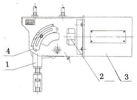
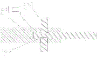
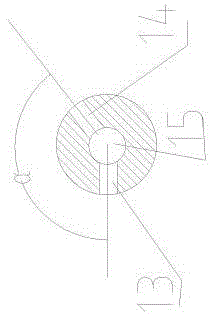
[0016] As shown in the figure, in order to solve the above-mentioned technical problems, the present invention provides a constant force suspension, which includes a housing 3, a pull rod assembly 2, a locking device 4 and a load assembly 1, and the pull rod assembly 2 is arranged laterally on the housing 3, one end of the tie rod assembly 2 is connected to the load assembly 1, and the tie rod assembly 2 is vertically arranged with the load assembly. The load assembly 1 includes an upper pull rod 10 and a lower pull rod 11. Longitudinal counterbore 15 is provided, internal thread is provided in described longitudinal counterbore 15, and external thread is provided on the outer circumference of described pull-down rod 11, and described upper and lower pull-down rod 10,11 are integrally connected by thread, and described longitudinal counterbore The hole wall of 15 is radial...


PUM


Abstract

The invention discloses a constant support and hanger which comprises a shell, a pull rod assembly, a locking device and a load assembly. The load assembly comprises an upper pull rod and a lower pull rod, a longitudinal counter bore is formed in the lower end of the upper pull rod, inner threads are arranged in the longitudinal counter bore, outer threads are arranged on the periphery of the lower pull rod, the upper pull rod and the lower pull rod are connected to form a whole through the threads, a first transverse through hole and a second transverse through hole are transversely formed in the bore wall of the longitudinal counter bore in the radial direction, the center line of the first transverse through hole and the center line of the second transverse through hole are both perpendicular to the center line of the longitudinal counter bore, and an included angle alpha is formed between the center line of the first transverse through hole and the center line of the second transverse through hole and is an obtuse angle. Grooves corresponding to the first transverse through hole and the second transverse through hole respectively are formed in the peripheral face of the upper end of the lower pull rod. When connection is carried out, transverse rods are inserted into the first transverse through hole and the second transverse through hole respectively, and one end of each transverse rod is inserted into the corresponding groove. The constant support and hanger is convenient to use and firm in connection.

Description

technical field [0001] The invention relates to a support and hanger, in particular to an anti-corrosion and wear-resistant constant force spring support and hanger. Background technique [0002] The constant force spring hanger is designed according to the principle of moment balance. Under the allowable load displacement, the load moment and spring moment are always in balance. For pipelines and equipment supported by constant force spring hangers, when displacement occurs, it can provide a constant supporting force, so it will not bring additional stress to pipeline equipment. Constant force spring supports and hangers are generally used in places where displacement stress needs to be reduced, such as power plant boiler bodies, suspension parts such as steam, water, smoke, air pipes and burners in power plants, and such supports are required in petroleum and chemical industries. The place. [0003] A traditional constant force support and hanger includes a housing, a p...

Claims


Application Information

Patent Timeline
Patent Type & Authority Applications(China)
IPC IPC(8): F16L3/16
CPCF16L3/16
Inventor 高勇
Owner JIANGSU DALICHENG ELECTRICAL
Why Eureka
Try Eureka