
A high-speed radar stap method under accelerated motion

An accelerated motion and high-speed technology, applied in the electronic field, can solve problems such as the difficulty of clutter suppression, and achieve the effect of suppressing system performance loss

Active Publication Date: 2017-01-04
GUANGXI UNIV
View PDF5 Cites 0 Cited by
  • Summary
  • Abstract
  • Description
  • Claims
  • Application Information

AI Technical Summary

Problems solved by technology

[0004] The present invention is to overcome the technical defect of the above-mentioned prior art that the accelerated motion of the high-speed radar leads to the difficulty of clutter suppression, and invented a high-speed radar STAP method under the state of accelerated motion

Method used


Image

  • A high-speed radar stap method under accelerated motion
  • A high-speed radar stap method under accelerated motion
  • A high-speed radar stap method under accelerated motion

Examples


Embodiment Construction

[0042] A specific embodiment of the present invention will be described in detail below in conjunction with the accompanying drawings, but it should be understood that the protection scope of the present invention is not limited by the specific embodiment.

[0043] space-time signal model

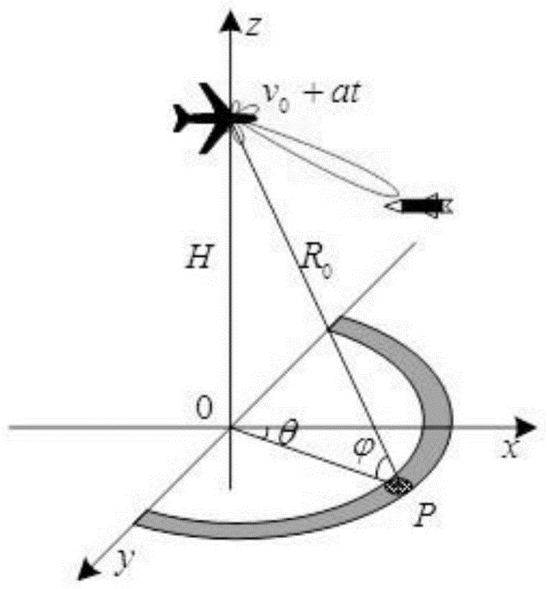
[0044] The radar look-down working configuration is as follows: figure 1 shown. The normalized vector of platform motion velocity direction is v=(v x ,v y ,v z ) T (||v||=1), the velocity vector can be expressed as (v 0 +at k )v. space The direction vector corresponding to the direction is θ and are the azimuth and elevation angles, respectively. Assuming that the number of radar airspace channels is M, the position of the array element is expressed as s=(s 1 ,s 2 ,...,s M ), where s m =(s mx ,s my ,s my ) T is the position vector of the mth array element. Assume that the echo signal received by the mth array element for the kth pulse is x mk (t-τ(m,k)), for the co...


PUM


Abstract

The invention discloses a STAP method for high-speed radar in an accelerated motion state. The method includes 1) acquiring the covariance gap matrix of the clutter of an arbitrary range gate; 2) analyzing the factors causing the clutter to diffuse along the Doppler domain; 3) Use time-domain covariance matrix tapering to describe the Doppler spread caused by acceleration; 4) Taper the time-domain covariance matrix Rt for clutter suppression, so that the space-time processor notch widens to suppress Doppler spread clutter ; 5) Obtain the tapering matrix T; 6) Obtain the relative space-time adaptive weight based on the tapering of the covariance matrix. This method determines the taper coefficient according to the Doppler bandwidth caused by acceleration, and performs the Hadamard product with the estimated covariance matrix, so that the notch of the space-time processor is widened along the Doppler direction, and the clutter caused by acceleration is suppressed along the Doppler direction. System performance loss caused by dimension widening.

Description

technical field [0001] The invention relates to the field of electronic technology, in particular to a high-speed radar STAP method in an accelerated motion state. Background technique [0002] In modern warfare, precision-guided weapons have increasingly become the main lethal weapons on the battlefield and play a decisive role in warfare. Low-altitude intrusion targets usually complete the intrusion with the help of a strong ground clutter background, and their interception and strike tasks pose great challenges to early warning radars. When the high-speed platform looks down, it faces the ground clutter with strong Doppler broadening and scattering intensity. How to effectively suppress the clutter has become a key issue for the high-speed platform early warning radar to complete low-altitude and ground target detection. [0003] The high-speed radar works in the forward-looking mode. At this time, the non-uniform distribution of clutter and the serious distance dependen...

Claims


Application Information

Patent Timeline
Patent Type & Authority Patents(China)
IPC IPC(8): G01S7/36
Inventor 文珺许京伟徐艳红覃玉荣赵进创
Owner GUANGXI UNIV
Learn More