
Multifunctional practical welding operation frame

A multi-functional, operating frame technology, applied in the direction of educational appliances, instruments, teaching aids, etc., can solve the problems of differential treatment, weak spot welding, unfavorable direct welding teaching of various welding subjects, etc., to achieve comprehensive functions and fixed connection methods Strong and meet the requirements of many different welding subjects

Inactive Publication Date: 2014-10-08
北京科技高级技术学校
View PDF7 Cites 2 Cited by
  • Summary
  • Abstract
  • Description
  • Claims
  • Application Information

AI Technical Summary

Problems solved by technology

[0006] 3. The direct welding point of the weldment is fixed on the traditional welding operation frame. Often the spot welding is not firm and falls and hurts people, or it cannot be easily taken off after too much spot welding;
[0007] 4. It cannot meet the welding of welds with different horizontal fixation, vertical fixation, and 45° oblique welding positions, and cannot simulate the welding use frame in complex spaces;
[0008] 5. For different welder heights, the welding of welds of different heights cannot be satisfied, which is not conducive to the differential treatment of student heights and weldment positions during welding teaching;
[0009] 6. Welding of plates and tubes (large-diameter tubes and small-diameter tubes) cannot be performed;
[0010] 7. When welding small-diameter pipes, one-word obstacles and cross obstacles cannot be set according to different pipe diameters to simulate complex working environments;
[0015] To sum up, the traditional welding operation frame has single function, which is not conducive to the intuitive observation of students during the teaching process, and is not conducive to the direct welding teaching of various welding subjects, and its teaching effect is also affected

Method used


Image

  • Multifunctional practical welding operation frame
  • Multifunctional practical welding operation frame
  • Multifunctional practical welding operation frame

Examples


Embodiment 1

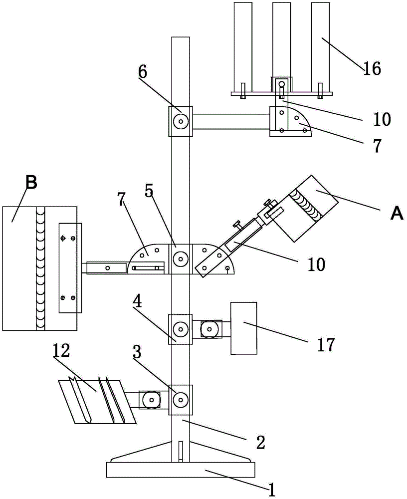
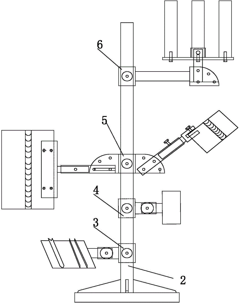
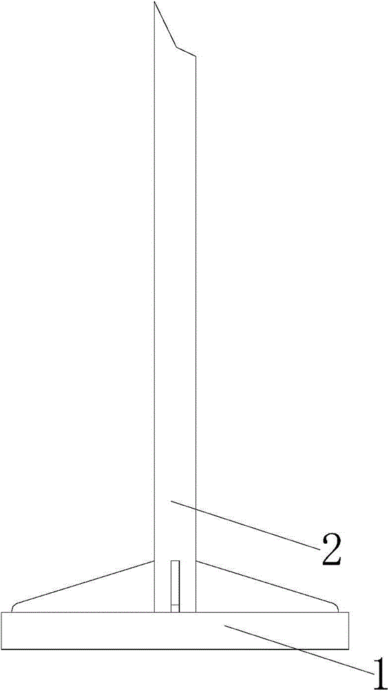
[0052] see figure 1 , a practical multifunctional welding operation frame provided by Embodiment 1 of the present invention includes a base 1 and a pillar 2 vertically and fixedly connected to the base (see also image 3and Figure 4 );

[0053] The four corners of the base 1 are provided with a plurality of through holes and are detachably connected to the ground through bolts;

[0054] There are also a first sleeve 3, a second sleeve 4, a third sleeve 5 and a fourth sleeve 6 sleeved at different heights from the bottom to the top of the pillar 2, and they are detachable from the pillar 2 respectively. Bolt connection; two ear plates 7 are also fixedly connected on the third sleeve 5; one ear plate 7 is also fixedly connected on the fourth sleeve 6; wherein the ear plate can be a single ear plate (see Figure 11 ) or double ear plate (see Figure 10 ); each said ear plate 7 is provided with a center positioning hole 8 and three angle adjustment holes 9 (see also Figure ...


PUM

PropertyMeasurementUnit
Diameteraaaaaaaaaa

Abstract

The invention discloses a multifunctional practical welding operation frame. The multifunctional practical welding operation frame comprises a base and a brace vertically and fixedly connected to the base. A plurality of through holes are formed in the four corners of the base, and bolts penetrate through the through holes so that the base can be detachably connected with the ground. A first sleeve, a second sleeve, a third sleeve and a fourth sleeve are connected to the positions, with different heights, of the brace from bottom to top in a sleeved mode, and respectively detachably connected with the brace through bolts, two lug plates are fixedly connected to the third sleeve, and a lug plate is fixedly connected to the fourth sleeve. One end of a cantilever tube is detachably connected with a first clamping end, a second clamping end, a small tube obstacle frame and a contra-aperture combined platform and other structural components through bolts, wherein the first clamping end is used for clamping plates of welder experiment current, and the second clamping end is used for clamping platy test pieces and large-tube-diameter test pieces.

Description

technical field [0001] The invention relates to the field of welding teaching equipment, in particular to a practical multifunctional welding operation frame. Background technique [0002] At present, there are 3,000 welding training institutions in vocational colleges, vocational schools, safety supervision, technical supervision and other departments in the country, and the welding operation frames used by training institutions are different in shape and function. The traditional welding operation frame in the prior art has simple structure and single function, and is simply fixed on the ground with a vertical pipe, and then a horizontal pipe is welded and fixed on the vertical pipe. [0003] However, there are many technical defects in such a crude traditional welding operation frame: [0004] 1. The vertical pipe of the traditional welding operation frame is directly buried under the ground and fixed, and cannot be moved later. It is very restricted in teaching, which i...

Claims


Application Information

Patent Timeline
IPC IPC(8): G09B19/00
Inventor 王影建张殿勇刘玉同安德新唐玉海
Owner 北京科技高级技术学校
Learn More