
passive external cooling system

An external cooling, passive technology, applied in the field of external cooling system, can solve the problems of increased water tank volume, waste, water overflowing the pile pit, etc., to achieve the effects of stable water injection flow, avoiding flow oscillation, and reducing cooling time

Active Publication Date: 2016-08-03
HARBIN ENG UNIV
View PDF8 Cites 0 Cited by
  • Summary
  • Abstract
  • Description
  • Claims
  • Application Information

AI Technical Summary

Problems solved by technology

[0005] However, the external cooling systems of the above designs all have a common shortcoming, that is, the utilization rate of cooling water is relatively low
When the water in the pile pit is full, if no one artificially closes the water pump or the control valve in the passive system, the water injection system will continue to inject water (regardless of the large or small flow rate), causing the water to overflow the pile pit and cause waste
Therefore, in order to ensure sufficient cooling time, without human intervention, the water tank of the above-mentioned passive cooling system needs to provide a large amount of water storage, which will greatly increase the volume of the water tank
However, if the water injection flow rate is too small, it may cause the water level in the reactor pit to drop, and even the reactor pressure vessel cannot be completely submerged, so that the reactor pressure vessel cannot be sufficiently cooled, thereby threatening the integrity of the reactor pressure vessel.
Therefore, if you do not want to cause additional loss of cooling water, but also provide continuous cooling for the pressure vessel, you need to manually adjust or start and stop the cooling system (whether it is an active system or a passive system), which will cause serious damage to the actual operation of the system. very difficult

Method used


Image

  • passive external cooling system

Examples


Embodiment Construction

[0014] The present invention is described in more detail below in conjunction with accompanying drawing example:

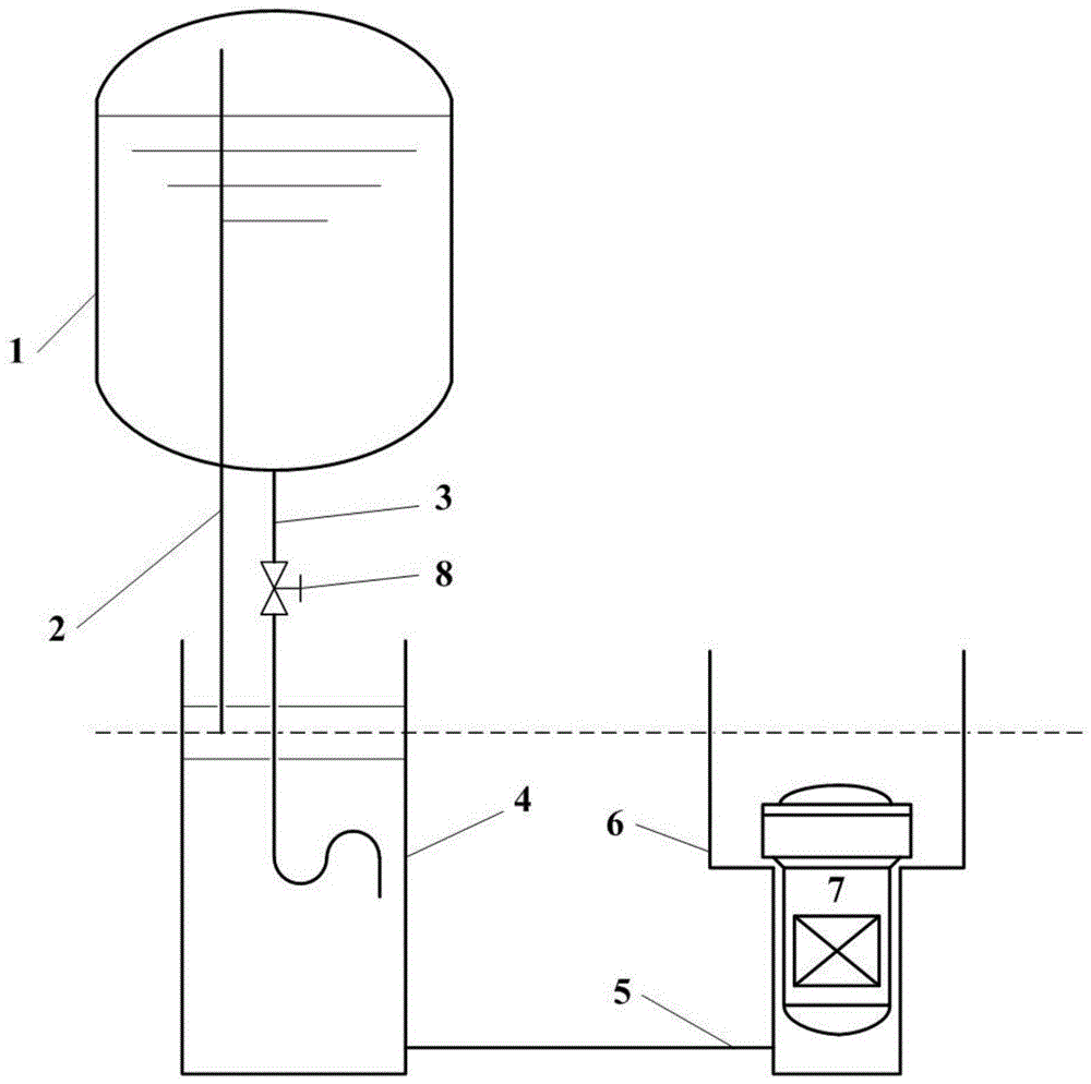
[0015] combine figure 1 , a passive external cooling system of the present invention mainly includes a water storage tank 1, a pressure balance pipe 2, a water injection pipe 3, an isolation pool 4, a connecting pipe 5, a reactor pit 6, a reactor pressure vessel 7 and a control valve 8. Wherein, the water storage tank 1 is located above the isolation pool 4, and the two are connected by a pressure balance pipe 2 and a water injection pipe 3, and the isolation pool 4 and the reactor pit 6 are connected by a communication pipe 5, and the reactor pressure vessel 7 is located in the reactor In the pile pit 6.

[0016] The upper end of the pressure balance pipe 2 is located in the air space of the water storage tank 1, and the relative position of the lower end is higher than the upper edge of the reactor pressure vessel 7. When the system is in a standby state, there...


PUM


Abstract

The invention aims at providing a passive out-of-reactor cooling system which comprises a water storage tank, an isolation water pool, a reactor pit and a reactor pressure container, wherein the water storage tank is positioned above the isolation water pool; the water storage tank is communicated with the isolation water pool through a water injection pipe and a pressure balance pipe; the reactor pressure container is positioned in the reactor pit; the isolation water pool is communicated with the reactor pit through a communicating pipe; the upper end of the pressure balance pipe is positioned in a gas space on the upper part of the water storage tank; the lower end of the pressure balance pipe is positioned in the isolation water pool; the height at which the lower end of the pressure balance pipe is positioned is greater than the height of the reactor pressure container; the upper end of the water injection pipe is communicated with the lowest point of the water storage tank; the lower end of the water injection pipe is positioned in the isolation water pool; the height of the lower end of the water injection pipe is smaller than that of the lower end of the pressure balance pipe. The passive out-of-reactor cooling system does not need external power support and can supply continuous cooling to the reactor pressure container under an accident working condition and can automatically supply water according to the consumption of cooling water in the reactor pit.

Description

technical field [0001] The invention relates to an external cooling system in the field of nuclear safety and thermal hydraulic technology. Background technique [0002] The reactor pressure vessel is a high-pressure device that plays an important role in containing and protecting the reactor core. When a serious reactor accident occurs in a nuclear power plant, the core melt may collapse to the lower head of the pressure vessel. If the lower head is melted due to excessive thermal load, it may threaten the integrity of the containment vessel. In order to avoid leakage of core melt and ensure the integrity of the reactor pressure vessel, an external cooling system needs to be installed so that the lower head can be fully cooled when an accident occurs. [0003] The currently installed external cooling system mainly has two configuration methods: active and passive. The active method mainly uses pumps to inject water into the pile pit to achieve cooling. Although the probabi...

Claims


Application Information

Patent Timeline
Patent Type & Authority Patents(China)
IPC IPC(8): G21C15/18
CPCY02E30/30
Inventor 范广铭孙秋南阎昌琪丁铭王建军曹夏昕谷海峰孙中宁郭子萱仝潘
Owner HARBIN ENG UNIV
Learn More