Electric wire bundling device

A wire and wire hole technology, which is applied in the field of wire tying devices, can solve problems such as leakage, aging of wire rubber, and difficulty in dissipating heat.

Inactive Publication Date: 2014-10-08
STATE GRID CORP OF CHINA +1
View PDF5 Cites 0 Cited by
  • Summary
  • Abstract
  • Description
  • Claims
  • Application Information

AI Technical Summary

Problems solved by technology

However, the wires will heat up during the power transmission process. When a large number of wires are bundled together, the multiple wires in the bundled part are close to each other, especially the wires located in th

Method used


Image

  • Electric wire bundling device

Examples


Example Embodiment

[0017] Example 1

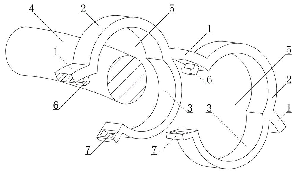
[0018] Such as figure 1 As shown, a wire binding device includes a plurality of single-wire binding mechanisms and a spacer 1 connecting two adjacent single-wire binding mechanisms, wherein the single-wire binding mechanism includes a static binding arm 2 and a movable binding arm 3. The movable binding arm 3 covers the static binding arm 2 and is combined with the static binding arm 2 to form a wire hole 5 for a single wire 4 to pass through. When in use, place the wire 4 at the position of the wire hole 5 between the movable tying arm 3 and the static tying arm 2, cover the movable tying arm 3, and set the wire 4 in the wire hole 5 In, and so on, the other wires 4 are also arranged in the other wire holes 5 in a one-to-one correspondence, so that the multiple scattered wires are tied together. Due to the existence of the spacer 1, a certain distance between the adjacent single-wire binding mechanisms can effectively prevent the adjacent wires from sticking ...

Example Embodiment

[0019] Example 2

[0020] The difference between embodiment 2 and embodiment 1 lies in: figure 1 As shown, one end of the static binding arm 2 is elastically connected with one end of the movable binding arm 3, and the other end of the static binding arm 2 is detachably connected with the other end of the dynamic binding arm 3. The two ends of the spacer 1 are respectively elastically connected to the two adjacent static binding arms 2. The movable tying arm 3, the static tying arm 2 and the spacer 1 are an integrally formed plastic structure. Therefore, the elastic connection means that the movable tying arm 3 is covered by the elasticity of the plastic. The movement of the static binding arm 2 and the relative bending movement of the two adjacent single-wire binding mechanisms.

[0021] The detachable connection is a live buckle connection between the buckle 6 provided at the other end of the static binding arm 2 and the buckle hole 7 provided at the other end of the movable bi...

Example Embodiment

[0022] Example 3

[0023] The difference between Embodiment 3 and Embodiment 2 is that one end of the static binding arm is hinged with one end of the movable binding arm, and two ends of the spacer are respectively hinged with two adjacent static binding arms. This situation is for the movable arm, static arm and spacer made of non-elastic materials, such as hard plastic or metal materials.

[0024] In other embodiments, one end of the spacer may be hinged, and the other end may be elastically connected.


PUM

PropertyMeasurementUnit
The inside diameter ofaaaaaaaaaa

Abstract

The invention provides an electric wire bundling device which comprises multiple single wire bundling mechanisms and spacing bars. Each spacing bar is connected between every two adjacent single wire bundling mechanisms. Each single wire bundling mechanism comprises a static bundling arm and a movable bundling arm, wherein the movable bundling arm covers the static bundling arm, the movable bundling arm and the static bundling arm jointly define an electric wire hole for a single electric wire to penetrate. Due to the spacing bars, a certain distance is reserved between two adjacent single wire bundling mechanisms, adjacent electric wires are effectively prevented from adhering and being gathered, heat produced in an electric wire gathering region is effectively radiated, and power supply safety is guaranteed. The electric wire bundling device has the advantages of being scientific in design and good in bundling effect and facilitating heat radiation.

Description

technical field [0001] The invention relates to a wire binding device, in particular to a wire binding device used in densely populated areas to facilitate heat dissipation. Background technique [0002] There will be a large number of wires in the distribution box or where the outdoor power transmission is relatively concentrated. In order to prevent the wires from being too messy and scattered, electric workers often bundle tree roots or dozens of wires together to achieve the purpose of neat wiring. However, the wires will heat up during the power transmission process. When a large number of wires are bundled together, the multiple wires in the bundled part are close to each other, especially the wires located in the middle of a bundle of wires are not easy to dissipate heat. Over time, it is easy to The aging of the wire rubber will cause electric leakage or even a fire. Therefore, this traditional bundling method has disadvantages. [0003] In order to solve the above...

Claims


Application Information

Patent Timeline
IPC IPC(8): H02G3/02
Inventor 刘锴王发义邹峰恩
Owner STATE GRID CORP OF CHINA
Why Eureka
Try Eureka