Hidden power distribution cabinet for smart home

A smart home and hidden technology, applied in substation/distribution device housing, electrical components, substation/switch layout details, etc., can solve the problems of affecting the appearance and occupying indoor space, so as to save space, avoid aesthetics, avoid The effect of low air pressure

Inactive Publication Date: 2020-12-01
胡立元
View PDF0 Cites 0 Cited by
  • Summary
  • Abstract
  • Description
  • Claims
  • Application Information

AI Technical Summary

Problems solved by technology

[0003] In the daily use of smart home, it is necessary to use the power distribution cabinet to coordinate the control circuits of each node. The existing power distribution cabinet is exposed and installed indoors, which not only affects the appearance, but also takes up valuable indoor space. It is urgent to design a smart Home hidden power distribution cabinet to solve the above problems

Method used


Image

  • Hidden power distribution cabinet for smart home
  • Hidden power distribution cabinet for smart home
  • Hidden power distribution cabinet for smart home

Examples


Embodiment 1

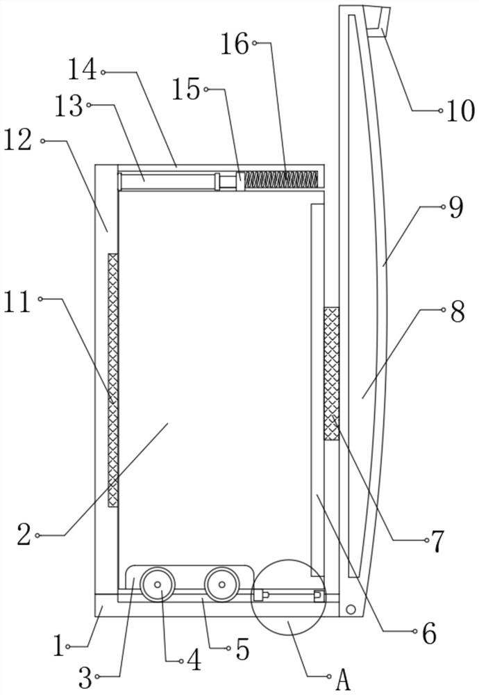
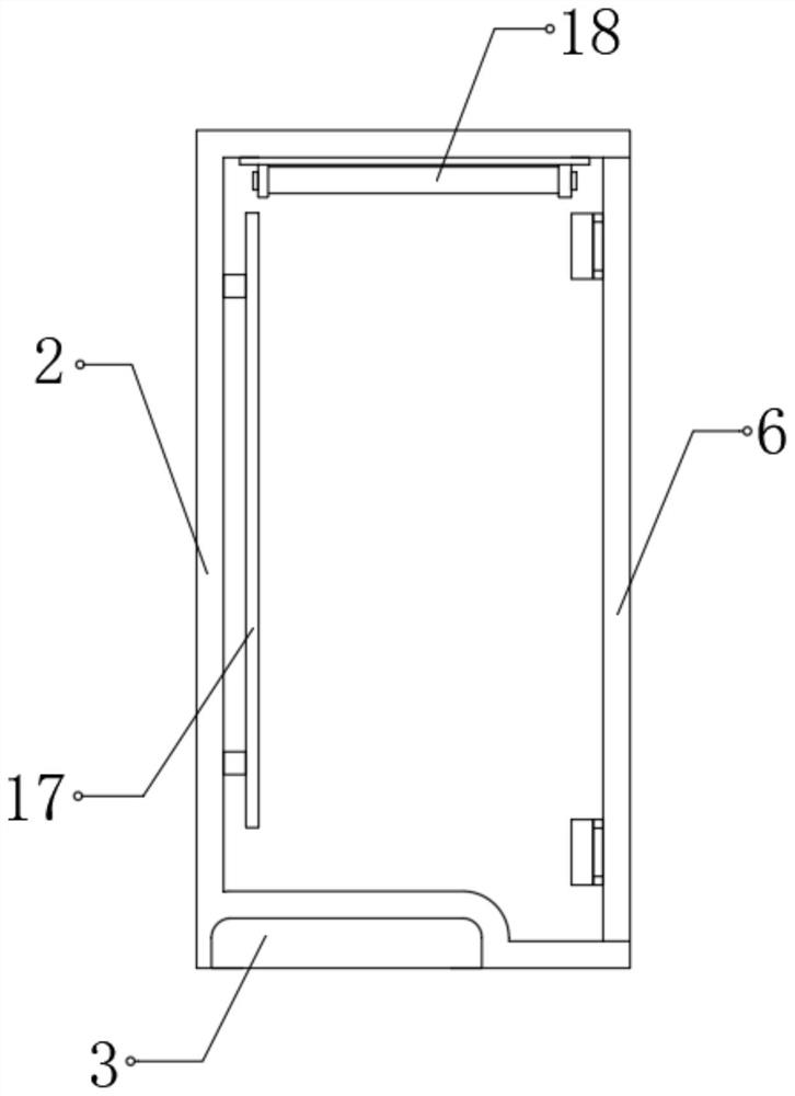
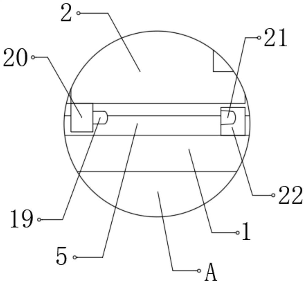
[0029] refer to Figure 1-4 , a hidden power distribution cabinet for smart homes, including a pallet 1 and a cabinet body 2, a limited slot 5 is provided on one side of the top of the pallet 1, and wheel grooves 3 are provided on both sides of the bottom of the cabinet body 2 , the insides of the two wheel grooves 3 are rotatably connected with rollers 4, and the rollers 4 are located inside the limit groove 5, the top of one side of the supporting plate 1 is fixedly connected with a backboard 12, and the top of the backboard 12 is fixedly connected with a cover Plate 14, the bottom of the cover plate 14 is provided with a groove, and the inner wall on one side of the groove is fixedly connected with a push rod motor 13, and one end of the push rod motor 13 is fixedly connected with a push plate 15, and the push plate 15 is fixedly connected to the cabinet body 2. On the outer wall of the top, one side of the supporting plate 1 is hinged with a rubber plate 9, and the inside ...

Embodiment 2

[0038] refer to Figure 5 , a hidden power distribution cabinet for smart homes. Compared with Embodiment 1, this embodiment has an L-shaped tube 23 inserted into the side of the rubber plate 9 close to the cabinet door 6, and the middle part of the L-shaped tube 23 is set There is a one-way ventilation valve 24, and the top end of the L-shaped pipe 23 is fixedly connected with a trachea joint 25.

[0039] Working principle: connect the air pipe joint 25 to the air pump, fill the cavity 8 with air, and the one-way ventilation valve 24 prevents air backflow. After the rubber plate 9 has been used for a long time, it can avoid insufficient air pressure inside the cavity 8. 23 is located between the rubber plate 9 and the cabinet door 6, and adopts a bending structure, which can effectively save space and avoid affecting the appearance of the wall.


PUM


Abstract

The invention discloses a hidden power distribution cabinet for smart home. The cabinet comprises supporting plates and a cabinet body; a limiting groove is formed in one side of the top of the supporting plate; roller grooves are formed in the two sides of the bottom of the cabinet body; rollers are rotationally connected to the interiors of the two roller grooves and the rollers are located in the limiting grooves; a back plate is fixedly connected to the top of one side of the supporting plate, a cover plate is fixedly connected to the top of the back plate, a groove is formed in the bottomof the cover plate, a push rod motor is fixedly connected to the inner wall of one side of the groove, and a push plate is fixedly connected to one end of the push rod motor. When the power distribution cabinet is used, the cabinet body is embedded in the wall body, the supporting plate, the back plate and the cover plate play a role in supporting the wall body, the cabinet body is hidden and protected, the occupied space of the cabinet body is saved, the rubber plate is exposed out of the wall body, the cavity is formed in the rubber plate, the influence of external impact on the cabinet body is buffered through air in the cavity, and power supply safety is guaranteed.

Description

technical field [0001] The invention relates to the technical field of smart home, in particular to a hidden power distribution cabinet for smart home. Background technique [0002] At present, smart home is based on the residence as a platform, and connects various devices in the home through the Internet of Things technology to realize an intelligent living environment. Smart home uses integrated wiring technology, network communication technology, security technology, automatic control technology, audio and video technology to integrate home life-related facilities to build an efficient management system for residential facilities and family schedules. [0003] In the daily use of smart home, it is necessary to use the power distribution cabinet to coordinate the control circuits of each node. The existing power distribution cabinet is exposed and installed indoors, which not only affects the appearance, but also takes up valuable indoor space. It is urgent to design a sm...

Claims


Application Information

Patent Timeline
Patent Type & Authority Applications(China)
IPC IPC(8): H02B1/30H02B1/38H02B1/40H02B1/44H02B1/54H02B1/56F17D1/07F17D3/01
CPCF17D1/07F17D3/01H02B1/30H02B1/38H02B1/40H02B1/44H02B1/54H02B1/565
Inventor 胡立元
Owner 胡立元
Why Eureka
Try Eureka