
Intelligent vehicle-mounted charger

An on-board charger, intelligent technology, applied in the direction of current collectors, electric vehicles, electrical components, etc., can solve the problems of single function, single function, multi-safety and other problems of on-board chargers, shorten charging time, protect batteries, and prolong usage The effect of longevity

Inactive Publication Date: 2014-10-08
BMZ COMPANY
View PDF7 Cites 6 Cited by
  • Summary
  • Abstract
  • Description
  • Claims
  • Application Information

AI Technical Summary

Problems solved by technology

[0002] At present, the commonly used car mobile phone charger is generally used by plugging it into the DC12V DC power supply of the car cigarette lighter. The charger includes a shell, a power contact, an indicator light, a power cord and a mobile phone plug. It is easy to use and plug in. Because the existing car charger has a single function, it only has a charging function. In addition, for the built-in audio equipment of the car produced in the past few years, the function is very single. Generally, the built-in player can only play the music stored in the memory. Files or music files stored in mobile devices or the installation of additional Bluetooth receivers to play audio files on smartphones or other mobile devices. Because using mobile phones to answer calls while driving is likely to bring more safety hazards, the current new traffic regulations require drivers to drive The penalty for using a mobile phone to make and receive calls is more serious. For this reason, we propose an intelligent car charger

Method used


Image

  • Intelligent vehicle-mounted charger
  • Intelligent vehicle-mounted charger
  • Intelligent vehicle-mounted charger

Examples


Embodiment Construction

[0012] The following will clearly and completely describe the technical solutions in the embodiments of the present invention with reference to the accompanying drawings in the embodiments of the present invention. Obviously, the described embodiments are only some, not all, embodiments of the present invention. Based on the embodiments of the present invention, all other embodiments obtained by persons of ordinary skill in the art without making creative efforts belong to the protection scope of the present invention.

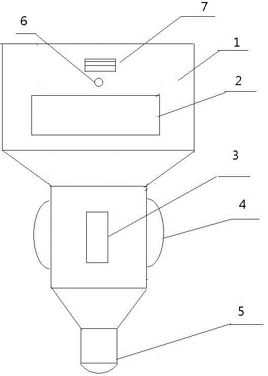
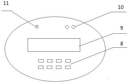
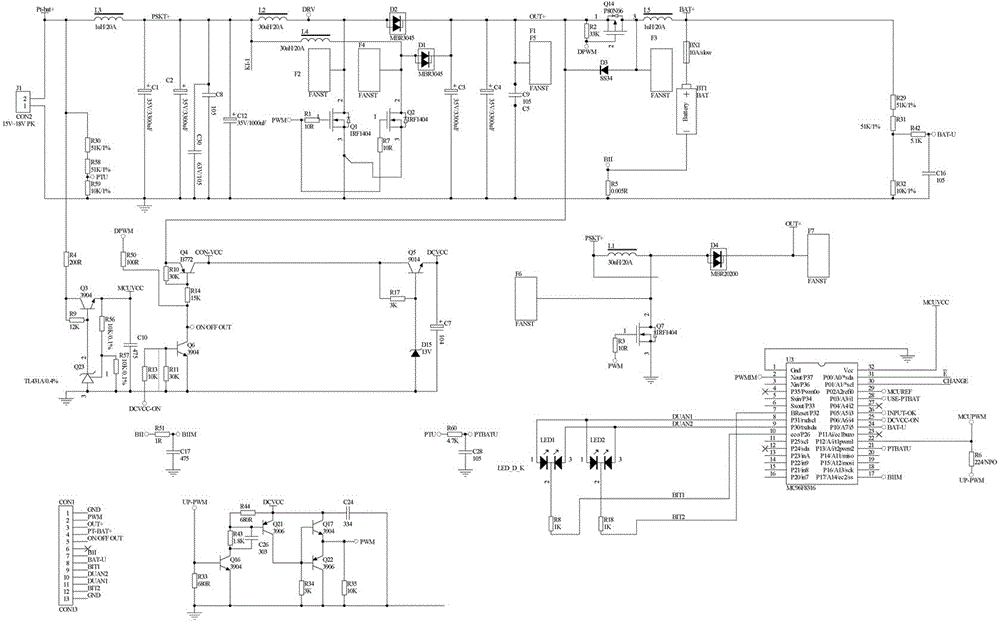
[0013] see Figure 1-3 , the present invention provides a technical solution: an intelligent vehicle charger, including a housing 1, an integrated control module 2, a voltage converter 3, a negative elastic buckle 4, a positive elastic head 5, an audio interface 6, and a charging data line USB interface 7, operation button 8, LCD digital display screen 9, LED charging indicator light 10 and call microphone 11, the interior of described housing 1 is installed w...


PUM


Abstract

The invention discloses an intelligent vehicle-mounted charger. The intelligent vehicle-mounted charger comprises a shell, an integrated control module, a voltage converter, negative-pole elastic buckles, a positive-pole elastic head, an audio interface, a charging data line USB interface, operating buttons, a digital LCD, LED charging indicator lights and a microphone. The integrated control module is mounted in the shell. The voltage converter is mounted in a cavity in the lower portion of the shell. The negative-pole elastic buckles are mounted on the side faces of the lower portion of the shell. The positive-pole elastic head is mounted at the bottom end of the shell. The audio interface and the charging data line USB interface are mounted on the side face of the upper end of the shell. According to the intelligent vehicle-mounted charger, after a vehicle is started, the shell of the vehicle-mounted charger is normally connected with a cigarette lighter socket and the vehicle-mounted charger is powered on, the green light of the LED charging indicator lights flickers to show that charging is normal, the audio interface is connected with a vehicular audio system through a data line, the Bluetooth function of a mobile phone and the Bluetooth function of the vehicle-mounted charger are set to achieve Bluetooth connection, and then the function of vehicle-mounted Bluetooth hands-free calls can be achieved.

Description

technical field [0001] The invention relates to the technical field of chargers, in particular to an intelligent vehicle charger. Background technique [0002] At present, the commonly used car mobile phone charger is generally used by plugging it into the DC12V DC power supply of the car cigarette lighter. The charger includes a shell, a power contact, an indicator light, a power cord and a mobile phone plug. It is easy to use and plug in. Because the existing car charger has a single function, it only has a charging function. In addition, for the built-in audio equipment of the car produced in the past few years, the function is very single. Generally, the built-in player can only play the music stored in the memory. Files or music files stored in mobile devices or the installation of additional Bluetooth receivers to play audio files on smartphones or other mobile devices. Because using mobile phones to answer calls while driving is likely to bring more safety hazards, th...

Claims


Application Information

Patent Timeline
IPC IPC(8): H02J7/00
Inventor 薜会民胡健财欧阳国金徐松
Owner BMZ COMPANY
Learn More