Shifting fork drilling fixture

A drilling fixture and fork claw technology, applied in the field of shifting fork drilling fixtures, can solve the problems of unstable clamping method, low processing efficiency, deformation, etc., and achieve the effects of good clamping effect, reasonable design and easy use.

Active Publication Date: 2014-10-15
青岛海博双木机械有限公司
View PDF9 Cites 6 Cited by
  • Summary
  • Abstract
  • Description
  • Claims
  • Application Information

AI Technical Summary

Problems solved by technology

The wall of this part is thin and easy to deform during the processing process, and the dimensional accuracy of the product is required to be high. In mass production, there are problems such as difficulty in ensuring processing ac

Method used


Image

  • Shifting fork drilling fixture
  • Shifting fork drilling fixture
  • Shifting fork drilling fixture

Examples


Embodiment Construction

[0017] Below in conjunction with accompanying drawing and specific embodiment the present invention is described in further detail:

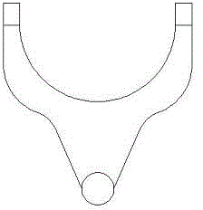
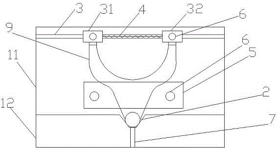
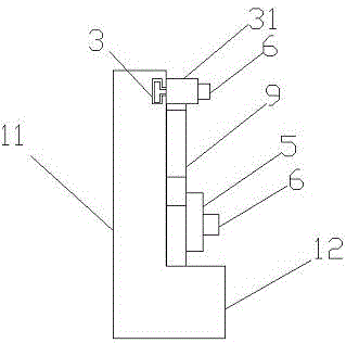
[0018] Such as figure 2 and 3 Said, a fork drilling jig of the present invention includes a chassis, the chassis includes a first bottom 11 and a second bottom 12, the thickness of the second bottom 12 is greater than the thickness 11 of the first bottom, the second The bottom 12 has a trapezoidal groove 2, and the first bottom 11 has a groove 3, and the groove 3 is equipped with a first positioning block 31 and a second positioning block 32 that can move freely in the groove 3, The first positioning block 31 and the second positioning block 32 are connected by a spring 4, the initial length of the spring 4 is less than the distance between the two claws of the shift fork 9, and the first bottom 11 is provided with a threaded hole. The pressure plate 5 is fixed on the first bottom 11 by screwing the bolt 6 into the threaded hole.

[0019] A ...


PUM


Abstract

The invention discloses a shifting fork drilling fixture. The shifting fork drilling fixture comprises a first bottom and a second bottom, the second bottom is thicker than the first bottom and provided with a trapezoidal groove, the first bottom is provided with a groove and a threaded hole, a first positioning block and a second positioning block which are movable are mounted in the groove and connected through a spring, the initial length of the spring is smaller than the distance between two fork claws of a shifting fork, and a pressure plate is screwed into the threaded hole through a bolt to be fixed onto the first bottom. The shifting fork drilling fixture is reasonable in design, simple in structure and effective in clamping; the fork claws of the shifting fork are fixed by the first positioning block and the second positioning block, and a fork shaft is fixed by the pressure plate, so that simplicity and convenience in use are achieved without damaging the shifting fork, and subsequent drilling is facilitated; due to the fact that positions of the first positioning block and the second positioning block are adjustable, the shifting fork drilling fixture is capable of meeting the clamping requirement of different specifications of shifting forks.

Description

technical field [0001] The invention belongs to the technical field of mechanical processing, and relates to a shift fork drilling jig. Background technique [0002] At present, there are a wide variety of products in the shift fork series of various models, with different specifications and a large output. A fork part such as figure 1 shown. The machining process of this part is as follows: Drilling and expanding the bottom hole of the boss - drawing the big hole of the boss - grinding the convex surface of the fork - correction - turning the arc groove - heat treatment of the fork - correction after heat - drilling pin hole. The wall of this part is thin and easy to deform during the processing process, and the dimensional accuracy of the product is required to be high. In mass production, there are problems such as difficulty in ensuring processing accuracy and low processing efficiency. Especially when drilling pin holes, the workpiece is usually clamped by a vise , ...

Claims


Application Information

Patent Timeline
IPC IPC(8): B23Q3/00
CPCB23Q3/069B23Q2703/02
Inventor 周建荣
Owner 青岛海博双木机械有限公司
Why Eureka
Try Eureka