direction indicator lights for vehicles

A technology for direction indicators and vehicles, applied in vehicle components, lighting and heating equipment, optical signals, etc., can solve problems such as reducing design, and achieve the effect of improving design and improving visibility

Inactive Publication Date: 2016-05-18
HONDA MOTOR CO LTD
View PDF7 Cites 0 Cited by
  • Summary
  • Abstract
  • Description
  • Claims
  • Application Information

AI Technical Summary

Problems solved by technology

Therefore, it is not preferable to provide the lens spectroscopic part on the outer lens, which tends to degrade the design.
[0006] In addition, as described in the above-mentioned Japanese Patent No. 4300927, if the light-emitting range is expanded by using the reflection based on the appearance surface formed on the partition wall, the entire appearance surface will emit light, and it will become the same as if there is no change in the intensity of light. There is still room for improvement in the way of light emission

Method used


Image

  • direction indicator lights for vehicles
  • direction indicator lights for vehicles
  • direction indicator lights for vehicles

Examples


no. 1 approach

[0036] Hereinafter, a first embodiment of the present invention will be described with reference to the drawings.

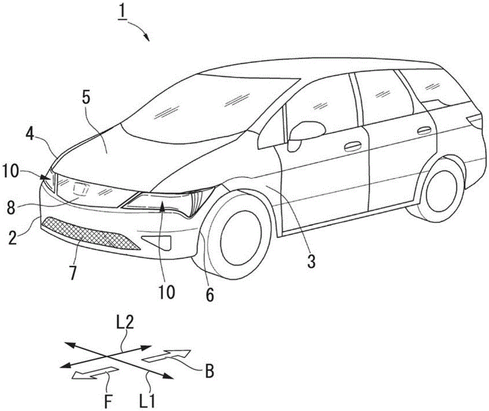
[0037] In addition, in this embodiment, a case where a vehicle winker is applied to a front turn signal (hereinafter, simply referred to as a turn signal) as a front winker provided at the front of a vehicle will be described as an example.

[0038] Such as figure 1 As shown, the front portion of a vehicle body 1 is covered with a front bumper 2 , left and right fenders 3 and 4 , a hood 5 , and the like. The front bumper 2 is formed so that its left and right ends go around the wheel arches 6 , and has a grille 7 at the lower part of the front surface for introducing traveling air into an engine room (not shown).

[0039] Above the front bumper 2, a front trim 8 is provided at the center in the vehicle width direction L1 between the front bumper 2 and the engine cover 5, and on both sides in the vehicle width direction L1 between the front bumper 2 and the engi...

no. 2 approach

[0087] Next, a second embodiment of the present invention will be described.

[0088] The difference from the first embodiment is that in the first embodiment, the reflector 22 is used as a light guide to guide the light from the turn signal body 20 to the inner lens 21 while reflecting it. In this method, an optical waveguide is used as a light guide. In addition, in this embodiment, the functional film 35 in the first embodiment is not formed.

[0089] (Structure of turn signal)

[0090] Such as Figure 7 As shown, the winker 40 (vehicle winker) of this embodiment is arranged toward the front F of the vehicle in a state where three rows of winker bodies 20 are mounted on a common control board 25 . Further, between the winker body 20 and the inner lens 21 , an optical waveguide 41 for guiding light from the winker body 20 to the inner lens 21 is arranged.

[0091] In addition, a light exit body 42 is formed by the inner lens 21 and the optical waveguide 41 .

[0092] Th...


PUM


Abstract

The invention provides a direction indicator light (13) for a vehicle, which has: a light source (20); It has: an outer injection surface (30) facing the outside of the vehicle; an inner injection surface (31) facing the inside of the vehicle; and a top end surface (32) facing the front or rear of the vehicle and connecting the two injection surfaces, the outer injection surface is formed by A first face (30a) facing the outside of the vehicle and a second face (30b) facing the front or rear of the vehicle are formed in a differential shape, and the first face and the second face are along the front-rear direction of the vehicle ( L2 ) are alternately and continuously arranged, and the light from the light source is emitted from the first surface to the outside, and is emitted from the second surface and the tip surface with stronger light intensity than from the first surface.

Description

technical field [0001] The present invention relates to a direction indicator lamp for vehicles. Background technique [0002] The light emitting range of the blinker lights for automobiles is specified in advance as a specification. In addition to the main light distribution emitted in the front direction (travel direction), in order to ensure conspicuousness, it is also required to be 45° inwardly and 80° outwardly. ° within the range of light. In order to meet such standards, various measures have been taken for vehicle blinkers. [0003] For example, if Figure 11 As shown, there is a known technique in which a lens cutportion 102 that refracts the light O from the light source 101 inward is formed on a part of the outer lens (outerlens) 100, whereby the light O is directed inwardly by 45°. shoot out. [0004] In addition, there is also known a technique in which an appearance surface that reflects light from a light source is provided on the surface of a partition wa...

Claims


Application Information

Patent Timeline
Patent Type & Authority Patents(China)
IPC IPC(8): B60Q1/34
CPCB60Q1/0041B60Q1/2607F21S43/14F21S43/26F21S43/239F21S43/243F21S43/245F21S43/40B60Q1/381F21S43/235
Inventor 渡边英史佐野友彦福良康二高山将之小万修二石桥洋绵贯茂佐川正浩
Owner HONDA MOTOR CO LTD
Why Eureka
Try Eureka