Two-wheeled vehicle lamp

Pending Publication Date: 2022-07-28
KOITO MFG CO LTD
View PDF0 Cites 0 Cited by
  • Summary
  • Abstract
  • Description
  • Claims
  • Application Information

AI Technical Summary

Problems solved by technology

Therefore, the number and arrangement positions of the light sources provided in the two-wheeled vehicl

Method used


Image

  • Two-wheeled vehicle lamp
  • Two-wheeled vehicle lamp

Examples


Embodiment Construction

[0023]Hereinafter, description is given of modes for carrying out a two-wheeled vehicle lamp according to the invention with reference to the attached drawings.

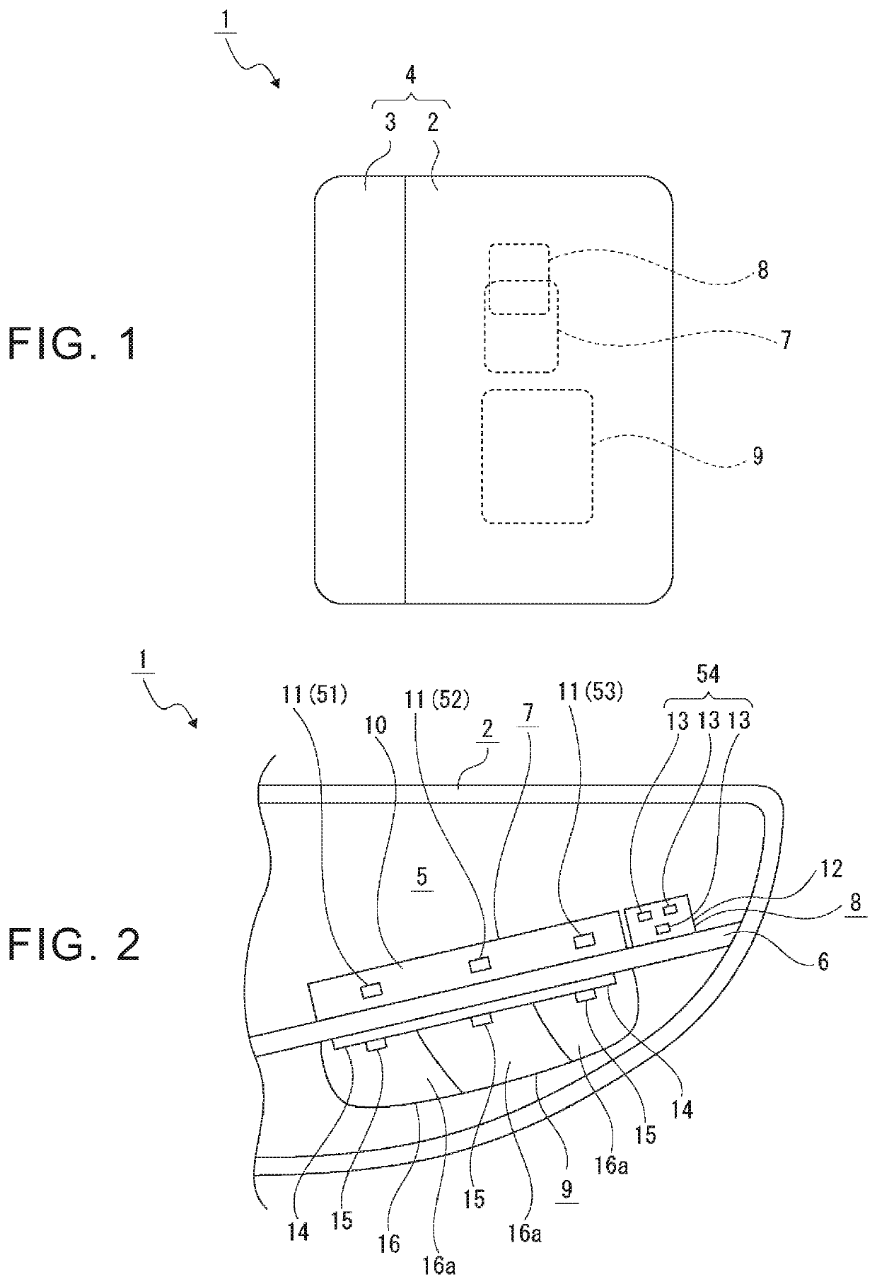
[0024]A two-wheeled vehicle lamp 1 is used as a so-called combination lamp that functions as, for example, both a turn signal lamp and a head lamp, and is arranged in and attached to, for example, a central portion of a front end portion of a vehicle body in a right-left direction.

[0025]The two-wheeled vehicle lamp 1 may be arranged in, for example, a rear end portion of the vehicle body as a combination lamp. When the two-wheeled vehicle lamp 1 is arranged in the rear end portion of the vehicle body, one two-wheeled vehicle lamp 1 may be arranged in the central portion in the right-left direction, or two two-wheeled vehicle lamps 1 may be arranged separately from each other on the right side and the left side, respectively. When the two-wheeled vehicle lamp 1 is arranged in the rear end portion of the vehicle body, the two-w...


PUM


Abstract

A first lamp unit and a second lamp unit arranged in a given direction are provided, luminous intensity of the second lamp unit in a lamp forward direction is set to be higher than luminous intensity of the first lamp unit in the lamp forward direction, and the first lamp unit and the second lamp unit are turned on sequentially with time difference. Thus, since the first lamp unit and the second lamp unit having different luminous intensity and being arranged in the given direction are turned on sequentially with time difference, it is visually recognized that emitted light flows from one side to the other, and the light is emitted from both the first lamp unit and the second lamp unit that has higher luminous intensity than that of the first lamp unit. Thus, it is possible to ensure high conspicuity in addition to improvement of functionality.

Description

TECHNICAL FIELD[0001]The invention relates to a technical field regarding a two-wheeled vehicle lamp that is used for a two-wheeled vehicle such as a motorcycle.BACKGROUND ART[0002]As a two-wheeled vehicle lamp having a lamp unit used as a turn signal lamp in a two-wheeled vehicle such as a motorcycle, there is a so-called sequential-type two-wheeled vehicle lamp in which a plurality of light sources that emit light is arranged, and the light is emitted from the light sources sequentially with time difference in an alignment direction of the light sources (for example, see Patent Document 1).[0003]With this type of two-wheeled vehicle lamp, it is visually recognized that the light flows from one side to the other in the alignment direction of the light sources, and high functionality is thus secured.[0004]Patent Document 1: WO2019 / 44404[0005]Incidentally, even in a state where the above-described sequential function is performed, it is desirable that high conspicuity should be ensur...

Claims


Application Information

Patent Timeline
IPC IPC(8): B60Q1/00B60Q1/38B62J6/026B62J6/056
CPCB60Q1/0041B60Q1/38B60Q2900/40B62J6/056B62J6/026B60Q1/381H05B47/16H05B47/155
Inventor HIKOSAKA, RIRIISHIHARA, YUJI
Owner KOITO MFG CO LTD
Why Eureka
Try Eureka