Combined flat beam

A technology of flat beams and steel beams, which is applied in the field of composite flat beams, can solve the problems of insufficient effectiveness and reliability of shear force transmission between steel and concrete, and the height does not reach the optimal effect, so as to simplify the construction process, optimize economy, The effect of improving fire resistance

Inactive Publication Date: 2014-10-15
TONGJI UNIV
View PDF8 Cites 9 Cited by
  • Summary
  • Abstract
  • Description
  • Claims
  • Application Information

AI Technical Summary

Problems solved by technology

[0005]Aiming at these disadvantages of composite beams, European scholars proposed the concept of composite flat beams at the end of last century, and new forms of composite flat beams (slimfor, slimdek, etc.) also emerged

Method used


Image

  • Combined flat beam
  • Combined flat beam
  • Combined flat beam

Examples


Embodiment Construction

[0031] The present invention will be further described below in conjunction with the embodiments shown in the accompanying drawings.

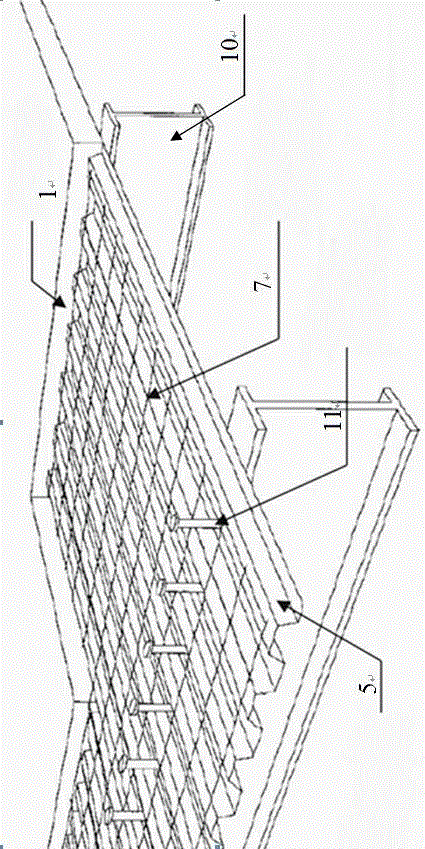
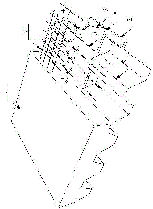
[0032] Such as figure 2 Described novel composite flat beam, its structure is:

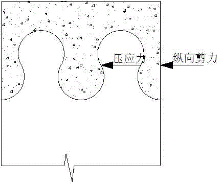
[0033] Including a steel beam, the steel beam includes a steel beam lower flange 2 and a steel beam web 3, which is an inverted T shape (or inverted π shape) composed of a steel beam lower flange 2 and a steel beam web 3, and the steel beam The lower flange 2 and the steel beam web 3 are connected by a weld 8; the upper part of the steel beam web 3 has a zigzag shear connector 4, and the zigzag shear connector 4 is a composite flat beam The only shear transfer device, such as image 3 shown.

[0034] It includes a profiled steel plate 5, which is pressed in a concave-convex wave shape, and the concave part of the profiled steel plate 5 is directly placed on the lower flange 2 of the steel beam (it can also be welded on the lower flange 2 of the steel beam by sp...


PUM


Abstract

The invention belongs to the field of structural engineering of civil engineering and particularly relates to a combined flat beam which structurally comprises a steel beam, pressing steel plates, concrete and shear reinforcements, wherein the steel beam is inverted T-shaped and composed of a steel beam bottom flange and a steel beam web; the upper part of the steel beam web is provided with saw toothed shear connectors; the pressing steel plates are placed on the steel beam bottom flange; the concrete is poured in a closed space formed by the steel beam, the pressing steel plates and end sealing plates; the shear reinforcements are arranged among the saw toothed shear connectors, and one or more shear reinforcements can be placed in each interval. The combined flat beam is greatly shorter than a traditional combined beam, so that the cost in structure, maintenance, equipment and labor is also reduced; the steel beam is coated with concrete, so that the fire-resistant performance of the combined structure is greatly improved, effective transmission of shearing force between steel and concrete is ensured, the construction technology is simplified, and excellent economy is realized.

Description

technical field [0001] The invention belongs to the field of civil engineering structure engineering, and in particular relates to a composite flat beam. Background technique [0002] At present, composite beams are widely used in building structures. It makes full use of the advantages of two materials (steel and concrete) to obtain greater rigidity and bearing capacity of the structure. Compared with reinforced concrete beams, the construction period of composite beams is shortened by 1 / 2~1 / 3, and the degree of construction disturbance is reduced, which has its incomparable advantages. [0003] like figure 1 As shown, in the traditional composite beam, the steel beam is on the bottom and mainly bears the tensile stress; the concrete is on the top and mainly bears the compressive stress. The transmission of the shear force between the steel beam and the concrete is realized through the shear connector—the peg 11, which ensures that the two materials work together in the f...

Claims


Application Information

Patent Timeline
IPC IPC(8): E04C3/293E04B1/94
Inventor 陈世鸣谭剑耀托伊
Owner TONGJI UNIV
Why Eureka
Try Eureka