
Multi-array LED chip for embodying cut-off line and head lamp having the same

A technology of LED chips and cut-off lines, which is applied in the direction of headlights, parts of lighting devices, semiconductor devices of light-emitting elements, etc., can solve the problems of reducing service life, loose joints and gaps, and reducing light efficiency, and achieves simplified structure. , Lightweight and simplified effect

Active Publication Date: 2014-10-15
HYUNDAI MOBIS CO LTD
View PDF7 Cites 6 Cited by
  • Summary
  • Abstract
  • Description
  • Claims
  • Application Information

AI Technical Summary

Problems solved by technology

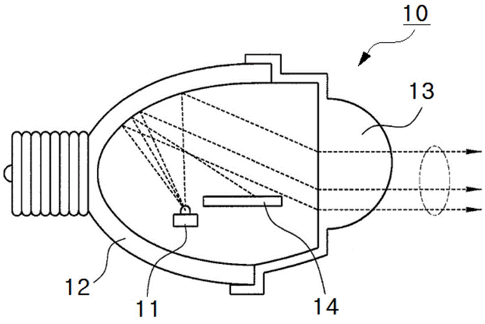
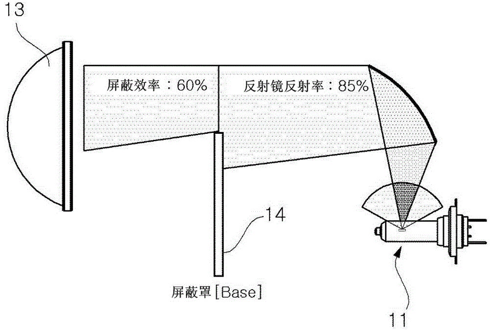
However, shielding 14 reduces light efficiency
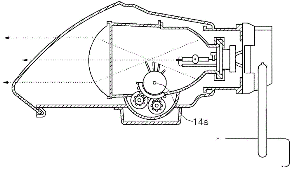
[0009] In particular, if image 3 As shown, when the headlight is equipped with a mechanical roller-shaped shield 14a, it will be accompanied by vibration, so looseness and gaps are likely to occur at the joint part, which reduces the service life and causes deformation of the joint structure
And, there is noise

Method used


Image

  • Multi-array LED chip for embodying cut-off line and head lamp having the same
  • Multi-array LED chip for embodying cut-off line and head lamp having the same
  • Multi-array LED chip for embodying cut-off line and head lamp having the same

Examples


Embodiment Construction

[0038] In order to clarify the solution to the technical problems of the present invention, the specific implementation manners of the present invention will be described in detail below in conjunction with the accompanying drawings. However, in the process of describing the present invention, if the description of related known technologies may obscure the gist of the present invention, the relevant description will be omitted. In addition, the terms described later are defined in consideration of the functions in the present invention, so different designers and manufacturers may have different definitions according to their own intentions or practices. Therefore, its definition shall be based on the contents of this specification. In addition, the same reference numerals (reference numbers) denote the same elements throughout the specification.

[0039] A multi-array LED chip (multi-array LED chip) 1 embodying a cut-off line according to an embodiment of the present invent...


PUM


Abstract

The present invention relates to a multi-array LED chip for embodying a cut-off line, and the multi-array LED chip includes: a plurality of LED modules which emits light; and at least one low beam LED module which emits light, in which the LED module and the low beam LED module are disposed to match a cut-off line, and the LED module and the low beam LED module are individually turned on and off such that a low beam is emitted. Accordingly, a direct type of light is emitted, and thus a low beam, which complies with regulations regarding the cut-off line, is embodied, and light efficiency does not deteriorate.

Description

technical field [0001] The present invention relates to a multi-array LED chip, specifically, the multi-array LED chip and headlights of a low beam (low beam) that can comply with cut-off line regulations by using the LED module of the multi-array LED chip to turn on and off. Background technique [0002] Generally speaking, in order to ensure the driver's field of vision when the surrounding illuminance is low, the car is equipped with a lighting device. Among them, the head lamp device is divided into a high beam device and a low beam device according to the difference in the irradiation angle and light quantity of the irradiated light. [0003] As the light source of headlights for automobiles, there are LED headlights using LED (light emitting diode). [0004] Here, LED (light emitting diode) is a diode that releases excess energy as light when injected electrons and holes recombine, and there are red light emitting diodes and green light emitting diodes. Due to its ad...

Claims


Application Information

Patent Timeline
Patent Type & Authority Applications(China)
IPC IPC(8): F21S8/10F21V19/00F21W101/10F21Y101/02
CPCF21S48/115F21S48/1154F21S48/1747F21K9/50F21S41/143F21S41/663F21S41/153F21S41/141F21S41/20F21V5/045F21W2102/00F21Y2115/10F21Y2105/10
Inventor 韩盛渊
Owner HYUNDAI MOBIS CO LTD
Learn More